


6. Cylinder Head / Valve
6-16
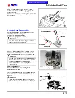
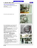
Valve Clearance Adjustment
Loosen Air Injection system (AI) pipe upper side
bolt (2 bolts).
Remove cylinder head cover.
Remove the cylinder head side cover.
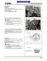
Remove left crankcase cover, and turn the drive
face, and align the timing mark on the cam
sprocket with that of cylinder head, piston is at
TDC position.
Loosen valve clearance adjustment nuts and bolts
located on valve rocker arm.
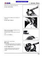
Measure and adjust valve clearance with feeler
gauge.
After valve clearance had been adjusted to
standard value, hold adjustment bolt and then
tighten the Adjustment nut.
Standard Value:
IN 0.10 ƒ 0.02 mm
EX 0.15 ƒ 0.02 mm
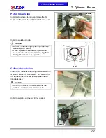
Install the cylinder head side cover.
Start the engine and make sure that engine oil
flows onto the cylinder head.
Stop the engine after confirmed, and then install
the cylinder head cover and AI pipe.
Caution
If lubricant does not flow to cylinder head,
engine components will be worn out seriously.
Thus, it must be confirmed.
When checking lubricant flowing condition, run
the engine in idle speed. Do not accelerate
engine speed.
To this chapter contents
4 bolts
3 bolts
2 bolts
Timing mark
Summary of Contents for Citycom.300i
Page 5: ...Serial Number Home page Contents...
Page 38: ...2 Maintenance Information 2 17 Note To this chapter contents...
Page 46: ...3 LUBRICATION SYSTEM 3 8 Notes To this chapter contents...
Page 106: ...4 Fuel Injection System 4 60 Note To this chapter contents...
Page 173: ...10 AC Generator Starting Clutch 10 10 Notes To this chapter contents...
Page 195: ...12 Cooling System 12 14 Notes To this chapter contents...
Page 223: ...14 Brake System 14 12 Note To this chapter contents...
Page 244: ...17 Electrical System 17 5 FUSE Fuse circuit diagram To this chapter contents...
Page 262: ...17 Electrical System 17 23 Note To this chapter contents...
Page 270: ...19 Electrical Diagram 19 1 Home page Contents LH30W EFi Electrical Diagram 19...


