


4. Fuel Injection System
4-29
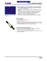
Ignition coil
First circuit coil
resistance
measurement
Functional Description:
●
Use 8 ~ 16V DC power supply, has the two-pin socket.
●
Two-pin socket for the power supply and grounding. Its main
components for the high conversion ratio transformer.
●
Through computer programs when the ignition is controlled, from
ignition timing (TDC) / crank position sensor, the throttle valve position
sensor, engine temperature sensor, the inlet pressure sensor and O
2
Sensor, issued by the signal, with the engine Speed through the ECU
to determine the appropriate ignition is, by the current of a crystal
intermittent control, a 25000-30000 volts of secondary hypertension,
flashover triggered spark plug, this approach will not only enable the
engine to achieve maximum output function, also help to improve the
efficiency of fuel consumption and pollution improvements.
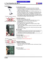
Testing Procedures:
Resistance Confirmation:
●
Removed coil first circuit plugs on the ignition coil (Red / Yellow &
Black / Yellow).
●
Use of the "meter" Ohm stalls (Ω), measurement of the ignition coil
resistance value.
Detection judge:
●
Ignition coil primary circuit:
2.8„15% Ω(20ƒC)
Treatment of abnormal phenomena:
1. Ignition coil internal coil disconnection damaged, or plugs bad contact.
2. Ignition coil ignition is not abnormal, proposes to replace the ignition
coil.
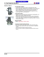
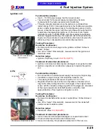
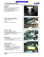
CPS
Measurement resistance value
Functional Description:
●
Do not need for an external power supply, has two-pin of signal plug.
●
Constitutes a major change in its reluctance induction coil.
●
The spacing of flywheel and sensor should be 0.7 to 1.1 mm.
●
Magnetic induction sensor is the use of flywheel on the Gear (23 +1
long tooth) rotary cutting induction coil changes in the magnetic field
sensor with the inductive voltage signal for ECU judgement, calculated
at the engine speed and crankshaft position, and with a most
appropriate time of fuel injection and ignition control.
Testing Procedures:
Resistance Confirmation:
●
Removed crankshaft position sensor coupler (Blue / Yellow & Green /
White).
●
Use of the "meter" Ohm stalls (Ω), measurement of the crankshaft
position sensor resistance value.
Detection judge:
●
Resistance value:
80~160Ω(20ƒC)
Treatment of abnormal phenomena:
1. Sensor internal coil interrupted damaged, or coupler bad contact.
2. Check whether the abnormal wire harness lines.
3. Sensor coil anomaly, the proposed replacement of the new one.
Long tooth
To this chapter contents
Summary of Contents for Citycom.300i
Page 5: ...Serial Number Home page Contents...
Page 38: ...2 Maintenance Information 2 17 Note To this chapter contents...
Page 46: ...3 LUBRICATION SYSTEM 3 8 Notes To this chapter contents...
Page 106: ...4 Fuel Injection System 4 60 Note To this chapter contents...
Page 173: ...10 AC Generator Starting Clutch 10 10 Notes To this chapter contents...
Page 195: ...12 Cooling System 12 14 Notes To this chapter contents...
Page 223: ...14 Brake System 14 12 Note To this chapter contents...
Page 244: ...17 Electrical System 17 5 FUSE Fuse circuit diagram To this chapter contents...
Page 262: ...17 Electrical System 17 23 Note To this chapter contents...
Page 270: ...19 Electrical Diagram 19 1 Home page Contents LH30W EFi Electrical Diagram 19...


