


8. V-Belt Driving System
8-10
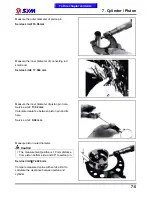
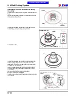
Clutch Outer/Driven Pulley
Disassembly
Remove drive belt, clutch outer and driven pulley.
Install clutch spring compressor onto the pulley
assembly, and operate the compressor to let the
wrench be installed more easily.
Caution
Do not press the compressor too much.
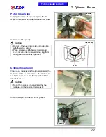
Hold the clutch spring compressor onto bench vise,
and then remove mounting nut with special service
tool.
Release the clutch spring compressor and remove
friction plate, clutch weight and spring from driven
pulley.
Remove seal collar from driven pulley.
Remove guide pin, guide pin roller, and movable
driven face, and then remove O-ring & oil seal
seat from movable driven face.
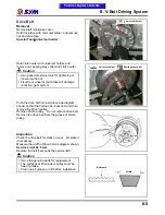
Inspection
Clutch outer
Measure the inner diameter of clutch outer.
Replace the clutch outer if exceed service limit.
Service limit: 145.450 mm
Clutch outer
Inner
diameter
O-ring
Guide pin roller
Guide pin
Seal
Movable driven face
Collar
Guide pin
Clutch spring compressor
Clutch nut wrench
To this chapter contents
Summary of Contents for Citycom.300i
Page 5: ...Serial Number Home page Contents...
Page 38: ...2 Maintenance Information 2 17 Note To this chapter contents...
Page 46: ...3 LUBRICATION SYSTEM 3 8 Notes To this chapter contents...
Page 106: ...4 Fuel Injection System 4 60 Note To this chapter contents...
Page 173: ...10 AC Generator Starting Clutch 10 10 Notes To this chapter contents...
Page 195: ...12 Cooling System 12 14 Notes To this chapter contents...
Page 223: ...14 Brake System 14 12 Note To this chapter contents...
Page 244: ...17 Electrical System 17 5 FUSE Fuse circuit diagram To this chapter contents...
Page 262: ...17 Electrical System 17 23 Note To this chapter contents...
Page 270: ...19 Electrical Diagram 19 1 Home page Contents LH30W EFi Electrical Diagram 19...


