


2-32 PERIODIC MAINTENANCE
COMPRESSION PRESSURE CHECK
The compression pressure reading of a cylinder is a good indicator of its internal condition.
The decision to overhaul the cylinder is often based on the results of a compression test. Periodic mainte-
nance records kept at your dealership should include compression readings for each maintenance service.
&
Compression pressure:
Standard: 1 000 kPa (10.0 kgf/cm², 142 psi)
(Automatic decompression actuated)
Low compression pressure can indicate any of the following conditions:
* Excessively worn cylinder walls
* Worn piston or piston rings
* Piston rings stuck in grooves
* Poor valve seating
* Ruptured or otherwise defective cylinder head gasket
NOTE:
When the compression pressure goes below specification, check the engine for conditions listed above.
COMPRESSION TEST PROCEDURE
NOTE:
* Before testing the engine for compression pressure, make
sure that the cylinder head nuts are tightened to the specified
torque and the valves are properly adjusted.
* Warm up the engine before testing.
* Make sure that the battery is fully charged.
Remove the related parts and test the compression pressure in
the following manner.
• Remove the seat. (
$
8-6)
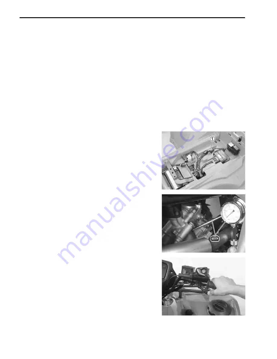
• Remove the fuel pump relay coupler
1
.
• Remove the spark plug. (
$
2-7)
• Install the compression gauge and adaptor in the spark plug
hole. Make sure that the connection is tight.
• Keep the throttle lever in the fully open position.
• Push the starter button and crank the engine for a few sec-
onds. Record the maximum gauge reading as the cylinder
compression.
%
09915-64512: Compression gauge set
09913-10750: Adaptor
NOTE:
After checking the compression test, clear the DTC using SDS
tool. (
$
5-23)
Summary of Contents for LT-A450X
Page 2: ...SUPPLEMENTS LT A450XK9 09 MODEL LT A450XK8 12 13 WIRING DIAGRAM 14 ...
Page 47: ...PERIODIC MAINTENANCE 2 29 ...
Page 48: ...2 30 PERIODIC MAINTENANCE ...
Page 63: ...ENGINE 3 7 Remove the engine mounting nuts Remove the engine from the right side ...
Page 215: ......
Page 315: ...7 24 COOLING AND LUBRICATION SYSTEM ENGINE LUBRICATION SYSTEM To cylinder head OIL PUMP ...
Page 316: ...COOLING AND LUBRICATION SYSTEM 7 25 EXHAUST SIDE INTAKE SIDE ...
Page 317: ......
Page 332: ...8 14 CHASSIS REAR CARRIER Remove the rear carrier REAR BOX Remove the rear box 1 ...
Page 417: ......
Page 452: ...9 34 ELECTRICAL SYSTEM HEADLIGHT INSTALLATION Head light coupler Head light R Adjusting point ...
Page 484: ...10 26 SERVICING INFORMATION Rear box Rear fender Right mud guard Left mud guard ...
Page 510: ......
Page 514: ......


