


7-10 COOLING AND LUBRICATION SYSTEM
COOLING FAN THERMO-SWITCH
REMOVAL
• Remove the front fender. (
$
8-15)
• Drain engine coolant. (
$
2-14)
• Disconnect the cooling fan thermo-switch coupler
1
.
• Remove the cooling fan thermo-switch
2
.
INSPECTION
Check the thermo-switch closing or opening temperatures by
testing it at the bench as shown in the figure. Connect the
thermo-switch
1
to a circuit tester and place it in the water con-
tained in a pan, which is placed on a stove.
Heat the water to raise its temperature slowly and read the col-
umn thermometer
2
when the switch closes or opens.
%
09900-25008: Multi-circuit tester set
6
Tester knob indication: Continuity test (
5
)
&
Cooling fan thermo-switch operating temperature
Standard (OFF
→
ON): Approx. 93°C (199°F)
(ON
→
OFF): Approx. 87°C (189°F)
#
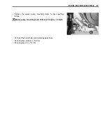
INSTALLATION
Install the cooling fan thermo-switch in the reverse order of
removal. Pay attention to the following points:
• Apply engine coolant to the O-ring
1
.
#
• Tighten the cooling fan thermo-switch to the specified torque.
"
Cooling fan thermo-switch: 17 N·m (1.7 kgf-m, 12.5 lb-ft)
• Connect the cooling fan thermo-switch coupler.
• Pour engine coolant. (
$
2-14)
* Take special care wh en h andling t he cooling f an
thermo-switch. I t may cau se damage if i t get s a
sharp impact.
* Do not contact the cooling fan thermo-switch and the
column thermometer with a pan.
The removed O-ring must be replaced with a new one
to prevent engine coolant leakage.
Summary of Contents for LT-A450X
Page 2: ...SUPPLEMENTS LT A450XK9 09 MODEL LT A450XK8 12 13 WIRING DIAGRAM 14 ...
Page 47: ...PERIODIC MAINTENANCE 2 29 ...
Page 48: ...2 30 PERIODIC MAINTENANCE ...
Page 63: ...ENGINE 3 7 Remove the engine mounting nuts Remove the engine from the right side ...
Page 215: ......
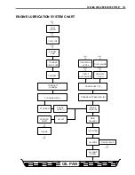
Page 315: ...7 24 COOLING AND LUBRICATION SYSTEM ENGINE LUBRICATION SYSTEM To cylinder head OIL PUMP ...
Page 316: ...COOLING AND LUBRICATION SYSTEM 7 25 EXHAUST SIDE INTAKE SIDE ...
Page 317: ......
Page 332: ...8 14 CHASSIS REAR CARRIER Remove the rear carrier REAR BOX Remove the rear box 1 ...
Page 417: ......
Page 452: ...9 34 ELECTRICAL SYSTEM HEADLIGHT INSTALLATION Head light coupler Head light R Adjusting point ...
Page 484: ...10 26 SERVICING INFORMATION Rear box Rear fender Right mud guard Left mud guard ...
Page 510: ......
Page 514: ......


