


3-104 ENGINE
• Install the generator rotor.
#
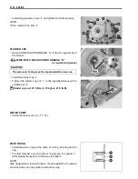
• Hold the generator rotor and tighten the generator rotor nut
5
to the specified torque with the special tool.
"
Generator rotor nut: 140 N·m (14.0 kgf-m, 101.5 lb-ft)
%
09924-62430: Long socket (22 mm)
TRANSFER OUTPUT DRIVE GEAR
• Install the spacer
1
.
• Install the transfer output drive gear
2
and snap ring
3
.
#
GEAR SHIFT
• Install the return spring
1
, washer
2
, gearshift cam stopper
3
, gearshift cam stopper bolt
4
.
NOTE:
Hook the return spring end
A
to the gearshift cam stopper.
#
• Tighten the gearshift stopper bolt securely.
• Install the gearshift cam stopper plate
5
.
NOTE:
Align the pin groove
A
of the gearshift cam stopper plate with
the pin of the gearshift cam.
• Tighten the gearshift cam stopper bolt securely.
Make su re t hat t he st arter cl utch o n t he c rankshaft
rotor is fitted into the generator rotor properly.
The removed snap ring must be replaced with a new
one.
Make su re t hat t he g earshift cam st opper mo ves
smoothly.
Summary of Contents for LT-A450X
Page 2: ...SUPPLEMENTS LT A450XK9 09 MODEL LT A450XK8 12 13 WIRING DIAGRAM 14 ...
Page 47: ...PERIODIC MAINTENANCE 2 29 ...
Page 48: ...2 30 PERIODIC MAINTENANCE ...
Page 63: ...ENGINE 3 7 Remove the engine mounting nuts Remove the engine from the right side ...
Page 215: ......
Page 315: ...7 24 COOLING AND LUBRICATION SYSTEM ENGINE LUBRICATION SYSTEM To cylinder head OIL PUMP ...
Page 316: ...COOLING AND LUBRICATION SYSTEM 7 25 EXHAUST SIDE INTAKE SIDE ...
Page 317: ......
Page 332: ...8 14 CHASSIS REAR CARRIER Remove the rear carrier REAR BOX Remove the rear box 1 ...
Page 417: ......
Page 452: ...9 34 ELECTRICAL SYSTEM HEADLIGHT INSTALLATION Head light coupler Head light R Adjusting point ...
Page 484: ...10 26 SERVICING INFORMATION Rear box Rear fender Right mud guard Left mud guard ...
Page 510: ......
Page 514: ......


