


3-94 ENGINE
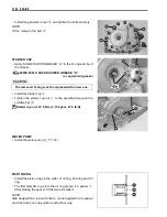
OIL SUMP FILTER
• Install the oil sump filter
1
.
NOTE:
Fit the projection
A
of the oil sump filter in the concave portion
of the crankcase.
CRANKCASE
• Thoroughly remove the sealant material and oil stains on the
mating surface of the right and left crankcase.
• Install the dowel pins
1
to the left crankcase.
• Apply engine oil to the conrod big end and each gear.
• Apply SUZUKI BOND “1215” to the mating surface of the right
crankcase as shown.
.
99000-31110: SUZUKI BOND “1215”
(or equivalent bond)
NOTE:
* Use of SUZUKI BOND “1215” is as follows: Make surfaces free
from moisture, oil, dust and other foreign materials.
* Spread on surfaces thinly to form an even layer, and assemble
the crankcases within few minutes.
* Take extreme care not to apply any BOND “1215” to the oil
hole, oil groove and bearing.
* Apply to distorted surfaces as it forms a comparatively thick
film.
• Tighten the crankcase bolts to the specified torque.
"
Crankcase bolt: (M6) 10 N·m (1.0 kgf-m, 7.0 lb-ft)
(M8) 26 N·m (2.6 kgf-m, 19.0 lb-ft)
#
NOTE:
Fit the clamp to the bolt
A
.
Tighten the larger diameter crankcase bolts first and
then smaller ones diagonally and evenly.
Summary of Contents for LT-A450X
Page 2: ...SUPPLEMENTS LT A450XK9 09 MODEL LT A450XK8 12 13 WIRING DIAGRAM 14 ...
Page 47: ...PERIODIC MAINTENANCE 2 29 ...
Page 48: ...2 30 PERIODIC MAINTENANCE ...
Page 63: ...ENGINE 3 7 Remove the engine mounting nuts Remove the engine from the right side ...
Page 215: ......
Page 315: ...7 24 COOLING AND LUBRICATION SYSTEM ENGINE LUBRICATION SYSTEM To cylinder head OIL PUMP ...
Page 316: ...COOLING AND LUBRICATION SYSTEM 7 25 EXHAUST SIDE INTAKE SIDE ...
Page 317: ......
Page 332: ...8 14 CHASSIS REAR CARRIER Remove the rear carrier REAR BOX Remove the rear box 1 ...
Page 417: ......
Page 452: ...9 34 ELECTRICAL SYSTEM HEADLIGHT INSTALLATION Head light coupler Head light R Adjusting point ...
Page 484: ...10 26 SERVICING INFORMATION Rear box Rear fender Right mud guard Left mud guard ...
Page 510: ......
Page 514: ......


