


5-40 FI SYSTEM DIAGNOSIS
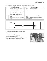
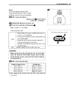
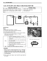
“C15” (P0115-H/L) ECT SENSOR CIRCUIT MALFUNCTION
INSPECTION
Step 1 (When indicating C15:)
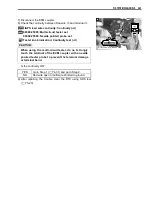
1) Remove the right side cover. (
$
8-10)
2) Turn the ignition switch to OFF.
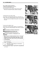
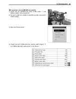
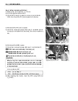
3) Check the ECT sensor coupler for loose or poor contacts.
If OK, then measure the ECT sensor voltage at the wire side
coupler.
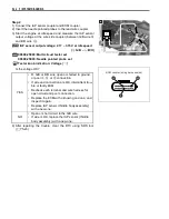
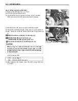
4) Disconnect the coupler and turn the ignition switch to ON.
5) Measure the voltage between B/Bl wire terminal
A
and
ground.
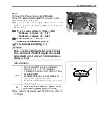
6) Also, then measure the voltage between B/Bl wire terminal
A
and B/O wire terminal
B
.
&
ECT sensor voltage: 4.5 – 5.5 V
(
+
B/Bl –
-
Ground)
(
+
B/Bl –
-
B/O)
%
09900-25008: Multi-circuit tester set
3
Tester knob indication: Voltage (
4
)
Is the voltage OK?
DETECTED CONDITION
POSSIBLE CAUSE
C15
Output voltage is not within the following
value.
0.15 < Sensor voltage
4.85 V
• ECT sensor circuit open or short.
• ECT sensor malfunction.
• ECM malfunction.
P0115
H
Sensor voltage is higher than specified
value.
• ECT sensor circuit open or ground circuit open.
• ECT sensor circuit shorted to ground.
L
Sensor voltage is lower than specified
value.
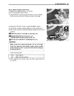
ECM
E2
ECT
B/O
ECT sensor
B/BI
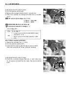
1
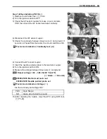
YES
Go to Step 2.
NO
• Loose or poor contacts on the ECM coupler.
(terminal
A
or
J
)
• Open or short circuit in the B/Bl wire or B/O
wire.
1
V
Summary of Contents for LT-A450X
Page 2: ...SUPPLEMENTS LT A450XK9 09 MODEL LT A450XK8 12 13 WIRING DIAGRAM 14 ...
Page 47: ...PERIODIC MAINTENANCE 2 29 ...
Page 48: ...2 30 PERIODIC MAINTENANCE ...
Page 63: ...ENGINE 3 7 Remove the engine mounting nuts Remove the engine from the right side ...
Page 215: ......
Page 315: ...7 24 COOLING AND LUBRICATION SYSTEM ENGINE LUBRICATION SYSTEM To cylinder head OIL PUMP ...
Page 316: ...COOLING AND LUBRICATION SYSTEM 7 25 EXHAUST SIDE INTAKE SIDE ...
Page 317: ......
Page 332: ...8 14 CHASSIS REAR CARRIER Remove the rear carrier REAR BOX Remove the rear box 1 ...
Page 417: ......
Page 452: ...9 34 ELECTRICAL SYSTEM HEADLIGHT INSTALLATION Head light coupler Head light R Adjusting point ...
Page 484: ...10 26 SERVICING INFORMATION Rear box Rear fender Right mud guard Left mud guard ...
Page 510: ......
Page 514: ......


