


5-44 FI SYSTEM DIAGNOSIS
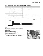
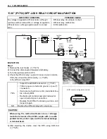
“C20” (P1752) DIFF-LOCK RELAY CIRCUIT MALFUNCTION
INSPECTION
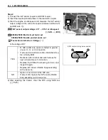
Step 1
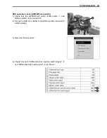
1) Remove the rear fender. (
$
8-15)
2) Connect the disconnected couplers and battery.
3) Turn the ignition switch to OFF.
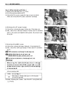
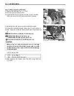
4) Check the diff-lock relay coupler for loose or poor contacts.
If OK, then check the diff-lock relay. (
$
9-25)
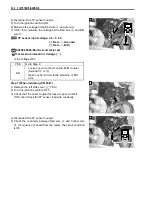
Is the diff-lock relay OK?
#
5) After repairing the trouble, clear the DTC using SDS tool.
(
$
5-23)
DETECTED CONDITION
POSSIBLE CAUSE
No voltage is applied to diff-lock motor, although
ignition switch is turned ON, or voltage is applied to
diff-lock motor, although ignition switch is turned
OFF.
• Diff-lock relay circuit open or short.
• Diff-lock relay malfunction.
• ECM malfunction.
YES
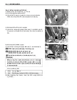
• Inspect the 4WD/diff-lock switch. (
$
9-37)
• Y/B wire open or shorted to ground, or poor
G
connection.
• If wire and connection are OK, intermittent trou-
ble or faulty ECM.
• Recheck each terminal and wire harness for
open circuit and poor connection.
• Replace the ECM with a known good one, and
inspect it again.
NO
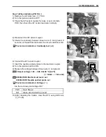
Replace the diff-lock relay with a new one.
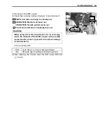
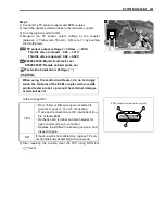
When us ing the multi-circuit te ster, do no t strongly
touch th e te rminal of the ECM c oupler with a ne edle
pointed te ster p robe t o pre vent th e te rminal da mage
or terminal bend.
ECM
DLR
Ignition
switch
Ignition
fuse
Main
fuse
Diff-lock relay
4WD/
diff-lock
switch
4WD/
diff-lock
actuator
4WD/
diff-lock
diode
O
B
W/Bl
Br
W
Y/B
B/G
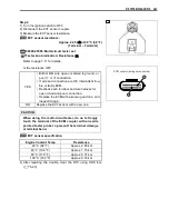
1
ECM coupler (wiring harness side)
Summary of Contents for LT-A450X
Page 2: ...SUPPLEMENTS LT A450XK9 09 MODEL LT A450XK8 12 13 WIRING DIAGRAM 14 ...
Page 47: ...PERIODIC MAINTENANCE 2 29 ...
Page 48: ...2 30 PERIODIC MAINTENANCE ...
Page 63: ...ENGINE 3 7 Remove the engine mounting nuts Remove the engine from the right side ...
Page 215: ......
Page 315: ...7 24 COOLING AND LUBRICATION SYSTEM ENGINE LUBRICATION SYSTEM To cylinder head OIL PUMP ...
Page 316: ...COOLING AND LUBRICATION SYSTEM 7 25 EXHAUST SIDE INTAKE SIDE ...
Page 317: ......
Page 332: ...8 14 CHASSIS REAR CARRIER Remove the rear carrier REAR BOX Remove the rear box 1 ...
Page 417: ......
Page 452: ...9 34 ELECTRICAL SYSTEM HEADLIGHT INSTALLATION Head light coupler Head light R Adjusting point ...
Page 484: ...10 26 SERVICING INFORMATION Rear box Rear fender Right mud guard Left mud guard ...
Page 510: ......
Page 514: ......


