


ENGINE 3-109
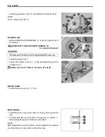
• Install the cam chain guide
3
.
NOTE:
Make sure that the cam chain guide
3
is inserted properly or
binding of the cam chain and guide may result.
• Install the dowel pins
4
and cylinder head gasket
5
.
#
CYLINDER HEAD
• With the head snugly seated on the cylinder, secure it by
tightening the bolts in diagonal stages. Tighten the cylinder
head bolts (M10) diagonally to the specified torque.
"
Cylinder head bolt (M10)
Initial: 25 N·m (2.5 kgf-m, 18.0 lb-ft)
Final: 37 N·m (3.7 kgf-m, 27.0 lb-ft)
NOTE:
* Apply engine oil to the threaded parts of the cylinder head
bolts (M10) and both sides of the its washers.
* Be sure to install the washer with rounded side facing up.
#
• After tightening the cylinder head bolts (M10) to specification,
tighten the cylinder head bolts (M8)
1
and cylinder base nuts
2
to the specified torque.
"
Cylinder head bolt (M8): 25 N·m (2.5 kgf-m, 18.0 lb-ft)
Cylinder base nut:
25 N·m (2.5 kgf-m, 18.0 lb-ft)
The removed gasket must be replaced with a new one
to prevent gas leakage.
The removed copper washers must be replaced to pre-
vent oil leakage.
Summary of Contents for LT-A450X
Page 2: ...SUPPLEMENTS LT A450XK9 09 MODEL LT A450XK8 12 13 WIRING DIAGRAM 14 ...
Page 47: ...PERIODIC MAINTENANCE 2 29 ...
Page 48: ...2 30 PERIODIC MAINTENANCE ...
Page 63: ...ENGINE 3 7 Remove the engine mounting nuts Remove the engine from the right side ...
Page 215: ......
Page 315: ...7 24 COOLING AND LUBRICATION SYSTEM ENGINE LUBRICATION SYSTEM To cylinder head OIL PUMP ...
Page 316: ...COOLING AND LUBRICATION SYSTEM 7 25 EXHAUST SIDE INTAKE SIDE ...
Page 317: ......
Page 332: ...8 14 CHASSIS REAR CARRIER Remove the rear carrier REAR BOX Remove the rear box 1 ...
Page 417: ......
Page 452: ...9 34 ELECTRICAL SYSTEM HEADLIGHT INSTALLATION Head light coupler Head light R Adjusting point ...
Page 484: ...10 26 SERVICING INFORMATION Rear box Rear fender Right mud guard Left mud guard ...
Page 510: ......
Page 514: ......


