Stober SD6 Series Manual Download Page 67

ID 442426.04

67

WE KEEP THINGS MOVING

Technical data

4

Manual SD6

4.12.2

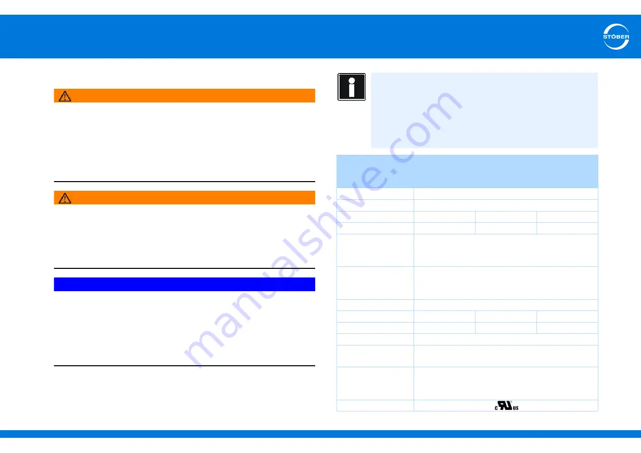
Output derater

WARNING!

Risk of burns! Fire hazard! Material damage!

Chokes can heat up to over 100 °C under permitted operating conditions.

Take protective measures against accidental and intentional contact with 

the choke.

Make sure that no flammable material is in the vicinity of the choke.

Do not install chokes under or near the drive controller. 

WARNING!

Fire hazard! 

Using chokes outside of the nominal data (cable length, current, frequency, 

etc.) can cause the chokes to overheat.

Always comply with the maximum nominal data when operating the 

chokes.

NOTICE

Danger of machine standstill! 

The motor temperature sensor evaluation is malfunctioning due to cable 

capacities.

If you use cables which are longer than 50 m and the cables are not from 

STOBER, the cores for the motor temperature sensor and the brake must 

be separate (maximum length: 100 m).

Information

The following technical data applies for a rotary field frequency of 

200 Hz. For example, this rotary field frequency is achieved with a 

motor with 4 pole pairs and a nominal speed of 3000 rpm.

Always observe the specified derating for higher rotary field 

frequencies. 

Also observe the dependency of the cycle frequency.

Type

TEP3720-

0ES41

TEP3820-

0CS41

TEP4020-

0RS41

ID no.

53188

53189

53190

Voltage range

3 x 0 to 480 V

Frequency range

0 to 200 Hz

I

N

 at 4 kHz 

4 A

17.5 A

38 A

I

N

 at 8 kHz 

3.3 A

15.2 A

30.4 A

Max. permitted motor 

cable length with 

output derater

100 m

Max. surrounding 

temperature 

ϑ


amb,max

40 °C

Design

Open

Winding losses

11 W

29 W

61 W

Iron losses

25 W

16 W

33 W

Connections

Screw terminals

Max. conductor 

cross-section 

10 mm

2

UL Recognized 

Component 

(CAN; USA) 

Yes

Test marks

Summary of Contents for SD6 Series

Page 1: ...SD6 Manual 442426 04 06 2015 en ...

Page 2: ...ation UL compliant use 10 3 Components of the drive system 15 4 Technical data 27 5 Transportation and storage 71 6 Installation 74 7 Connection 85 8 Basic properties 145 9 Drive controller 155 10 Motor 208 11 Holding brake 229 12 Encoder 249 13 Mechanical drive model 259 14 Communication 264 15 Optimize 295 16 Diagnosis 363 ...

Page 3: ...ons 1 Manual SD6 1 General instructions Overview of sections 1 1 About this manual 4 1 2 Further documentation 5 1 3 Further support 5 1 4 Directives and norms 5 1 5 Abbreviations formula symbols and indices 6 1 6 Symbols identifiers marks 8 1 7 Licenses 9 ...

Page 4: ...drive controller It contains information on the following topics Projecting Transport and storage Installation Connection Operation and setup of the drive controller motor and its attachments and the entire drive Communication between the startup computer and drive controller Optimization of the drive controller Diagnostics in the event of errors The safety function Safe Torque off STO is implemen...

Page 5: ...ective 2004 108 EC EN 61326 3 1 2008 EN 61800 3 2004 EN 61800 5 1 2007 EN 61800 5 2 2007 EN 50178 1997 Device software Documentation Contents ID SD6 drive controllers Commissioning instructions Installation and functional test 442537 Controller Based Mode CBM application Manual Operation and setup commissioning 442454 Communication module EtherCAT EC6 Operating manual Installation connection setup...

Page 6: ... Input output EMF Electromotive force EMC Electromagnetic Compatibility HTL High threshold logic I O Input Output IA Installation Altitude IGB Integrated Bus ip Interpolated position mode IP International Protection LS Limit Switch MAC Media Access Control MTF Motor temperature sensor PE Protective Earth PELV Protective Extra Low Voltage PLC Programmable Logic Controller dt SPS PTC Positive Temper...

Page 7: ...ent of the drive controller control board I1N PU A Nominal input current of the drive controller power board I2 A Output current I2max A Maximum output current I2maxPU A Maximum output current of the drive controller power board I2min A Minimum output current I2N PU A Nominal output current of the drive controller power board IN A Nominal current n rpm Speed nN rpm Nominal speed Speed at which the...

Page 8: ... λLine Power factor at the supply network equivalent to cos φ between the effective and apparent power Symbols EN 61558 2 20 Choke without overload protection Grounding symbol according to IEC 60417 5019 DB 2002 10 Identification and test symbols Lead free identifier for RoHS Lead free identifier according to RoHS directive 2011 65 EU CE mark Manufacturer s self declaration The product meets the r...

Page 9: ...en 11 D 40721 Hilden Germany Tel 49 2103 2878 0 Fax 49 2103 2878 28 E mail support segger com Internet http www segger com Trademarks CANopen CiA CANopen and CiA are registered Community trademarks of CAN in Automation e V Nuremberg Germany EnDat EnDat and the EnDat logo are registered trademarks of Dr Johannes Heidenhain GmbH Traunreut Germany EtherCAT EtherCAT and the EtherCAT logo are registere...

Page 10: ...information UL compliant use Overview of sections 2 1 Operation in accordance with its intended use 11 2 2 Component part of the product 11 2 3 Risk assessment 11 2 4 Qualified personnel 11 2 5 Working on the machine 12 2 6 Disposal 12 2 7 Presentation of notes on safety 12 2 8 UL compliant use 13 ...

Page 11: ...chine is disposed of If the product is sold disposed of or rented out always include the technical documentation with the product 2 3 Risk assessment Before the manufacturer may bring a machine onto the market he must conduct a risk assessment according to Machine Directive 06 42 EC As a result the risks associated with the use of the machine are determined The risk assessment is a multi stage and...

Page 12: ...astic Sheet metal Copper Aluminum 2 7 Presentation of notes on safety NOTICE Notice means that property damage may occur if the stated precautionary measures are not taken CAUTION Caution with warning triangle means that minor injury may occur if the stated precautionary measures are not taken WARNING Warning means that there may be a serious danger of death if the stated precautionary measures ar...

Page 13: ...ating surge voltage 4 kV peak phase phase or N 480 V permissible rating surge voltage 6 kV peak Motor protection All models of STOBER 6th generation drive controllers have a certified i t model a calculation model for thermal monitoring of the motor This fulfils the requirements for semiconductor motor overload protection in accordance with the change to UL 508C dated May 2013 To activate the prot...

Page 14: ...on Note also terminal description X101 pin 18 or 19 see section 7 4 2 Branch circuit protection An integral solid state short circuit protection does not provide branch circuit protection If you would like to branch the output of the drive controller branch circuit protection must be ensured in conformity with the instructions of STOBER the National Electrical Code and all additional applicable lo...

Page 15: ...s 18 3 2 1 Synchronous servo motors and asynchronous motors 18 3 2 2 Synchronous linear motors 18 3 3 Controller 19 3 4 Accessories 19 3 4 1 Safety technology 19 3 4 2 Terminal modules 20 3 4 3 Communication 22 3 4 4 DC link connection 24 3 4 5 Braking Resistors 24 3 4 6 Chokes 24 3 4 7 EMC shroud 25 3 4 8 Encoder adapter box 25 3 4 9 Battery module for encoder buffering 26 3 4 10 Removable data s...

Page 16: ... in the example Meaning Type SD6A06TEX Drive controller type according to the type designation Date 1318 Production week in format YYWW in the example shown here year 2013 week 18 S N 7000204 Serial number Nominal connection voltage 3 x 400 V 50 Hz UL 3 x 480 V 50 60 Hz Nominal connection voltage Nominal connection power 2 5 kVA Nominal connection power Input current 4 0 A Input current Output dat...

Page 17: ... T E X Code Designation Design SD Series Servo Drive 6 Generation 6 Generation A B Version 0 3 Size 0 9 Power output stage within the size T Safety module ST6 Safe Torque Off STO N E C Communication module Empty EC6 EtherCAT CA6 CANopen N X R I Terminal module Empty XI6 Extended I O RI6 Resolver I O IO6 Standard I O Type Size SD6A02 0 SD6A04 0 SD6A06 0 SD6A14 1 SD6A16 1 SD6A24 2 SD6A26 2 SD6A34 3 ...

Page 18: ... optical magnetic or inductive measurement system These measurement systems consist of a dimensional element or magnetic tape that determines the position of the motor through interaction with a read head or probe An additional linear encoder transfers this information to the drive controller as position data Depending on the key requirement in each specific case for example speed accuracy etc dif...

Page 19: ...This is equivalent to the safety function Safe torque off STO in accordance with DIN EN 61800 5 2 2007 This type of shutdown is designated as Stop category 0 in DIN EN 60204 1 2006 MC6 Motion Controller The development of the new MC6 Motion Controller and its integration into the STOBER product portfolio opens up new solutions for drive technology especially for complex functions with demanding re...

Page 20: ...ection 1 2 Further documentation 3 4 2 Terminal modules Terminal module XI6 ID no 138421 Terminal module for connecting analog and binary signals as well as encoders Supported inputs and outputs 13 binary inputs 24 V 10 binary outputs 24 V 3 analog inputs 10 V 1 x 0 20 mA 16 bits 2 analog outputs 10 V 12 bits Supported encoders interfaces SSI encoder simulation and evaluation TTL incremental encod...

Page 21: ...ferential simulation and evaluation TTL incremental encoder single ended evaluation HTL incremental encoder single ended simulation and evaluation TTL pulse train differential simulation and evaluation TTL pulse train single ended evaluation HTL pulse train single ended simulation and evaluation Interface adapter AP6 Encoder cables that were connected to a POSIDYN SDS 4000 can be connected via the...

Page 22: ...T connection and CA6 for the CANopen connection Terminal module IO6 ID no 138420 Terminal module for connecting analog and binary signals as well as encoders Supported inputs and outputs 5 binary inputs 24 V 2 binary outputs 24 V 2 analog inputs 10 V 1 x 0 20 mA 12 bits 2 analog outputs 10 V 20 mA Supported encoders interfaces HTL incremental encoder single ended simulation and evaluation HTL puls...

Page 23: ...Ethernet adapter ID no 49940 Adapter for connecting Ethernet to a USB connection EC6 communication module ID no 138425 Communication module for the EtherCAT connection EtherCAT cable EtherNet patch cable CAT5e yellow The following versions are available ID no 49313 approx 0 2 m ID no 49314 approx 0 35 m CA6 communication module ID no 138427 Communication module for the CANopen connection ...

Page 24: ...erent drive controllers STOBER offers corresponding braking resistors in different sizes and performance classes see 4 11 Braking Resistors 3 4 6 Chokes Chokes and coils that reduce the susceptibility of drive systems and offset interfering pulses They are thus used to protect components devices or power supplies and simultaneously increase their interference immunity and availability STOBER offer...

Page 25: ...onnect the cable shield of the braking resistor and DC link connection on the shroud Additional shield connection terminals are available as accessories for this purpose ID No 56521 Encoder adapter box LA6A00 ID no 56510 LA6 for connecting HIWIN TTL Encoder adapter box for transferring TTL and Hall sensor signals from HIWIN synchronous linear motors to the SD6 drive controller LA6 for the adaptati...

Page 26: ...ceable battery AES ID no 55453 Replaceable battery for Absolute Encoder Support AES Removable Data Storage Paramodule Included in the standard design ID no 56403 The plug in ParaModule with integrated microSD card 128 MB industrial is available as a storage medium The microSD card is also available separately as a spare part ID No 56436 Product CD STOBER ELECTRONICS 6 Included in the standard desi...

Page 27: ...g 33 4 3 Device features 33 4 4 Transportation storage and operating environment 34 4 5 Operating motors 35 4 5 1 Evaluatable encoders 36 4 5 1 1 Connection X4 36 4 5 1 2 Connection X120 37 4 5 1 3 Connection X101 binary input encoder 37 4 5 1 4 Connection X140 38 4 5 2 Controllable brakes 39 4 5 3 Evaluatable motor temperature sensors 39 4 6 Protective measures 40 4 6 1 Line fuse 40 4 6 2 Residua...

Page 28: ... 2 Power supply 53 4 10 3 Line fuse 54 4 10 4 Power contactor 55 4 10 5 Projecting 56 4 11 Braking Resistors 58 4 11 1 FZMU FZZMU 58 4 11 2 FGFKU 59 4 11 3 GVADU GBADU 61 4 11 4 Bottom brake resistor RB 5000 62 4 12 Chokes 63 4 12 1 Power choke 64 4 12 2 Output derater 67 ...

Page 29: ...network of this type Always operate the devices within the limits specified in the technical data The following applications are prohibited Use in areas subject to explosion hazard Use in environments with harmful substances as specified by EN 60721 for example oils acids gases vapors dust and radiation Implementation of the following applications is only permitted after approval is obtained from ...

Page 30: ...ype SD6A02 SD6A04 SD6A06 fPWM PU 4 kHza a Clock frequency adjustable from 4 to 16 kHz see section 4 2 2 5 Derating I1N PU 8 3 A 2 8 A 5 4 A I2N PU 4 A 2 3 A 4 5 A I2maxPU 180 for 5 s 150 for 30 s Type SD6A02 SD6A04 SD6A06 fPWM PU 8 kHza a Clock frequency adjustable from 4 to 16 kHz see section 4 2 2 5 Derating I1N PU 6 A 2 2 A 4 A I2N PU 3 A 1 7 A 3 4 A I2maxPU 250 for 2 s 200 for 5 s Type SD6A02 ...

Page 31: ... see section 4 2 2 5 Derating I1N PU 9 3 A 15 8 A I2N PU 6 A 10 A I2maxPU 250 for 2 s 200 for 5 s Type SD6A14 SD6A16 UonCH 780 800 V UoffCH 740 760 V R2minRB 47 Ω PmaxRB 13 6 kW 13 6 kW Type SD6A24 SD6A26 U1PU 3 400 V 32 50 50 60 Hz 3 480 V 10 58 50 60 Hz f2PU 0 700 Hz U2PU 0 max U1 PV PU I2 IN 220 W 280 W Type SD6A24 SD6A26 fPWM PU 4 kHza a Clock frequency adjustable from 4 to 16 kHz see section ...

Page 32: ...A Type SD6A34 SD6A36 SD6A38 U1PU 3 x 400 V 32 50 50 60 Hz 3 x 480 V 10 58 50 60 Hz f2PU 0 700 Hz U2PU 0 max U1 PV PU I2 IN 350 W 600 W 1000 W Type SD6A34 SD6A36 SD6A38 fPWM PU 4 kHza a Clock frequency adjustable from 4 to 16 kHz see section 4 2 2 5 Derating I1N PU 45 3 A 76 A 76 A I2N PU 44 A 70 A 85 Ab b Specification applies for the default setting of the field weakening voltage limit B92 80 I2m...

Page 33: ...ne the nominal current I2N PU 2 Determine the derating factors for installation altitude and surrounding temperature 3 Calculate the nominal output current I2N PU according to the following formula I2N PU I2N PU DT DIA A drive controller of type SD6A06 will be operated at a clock frequency of 8 kHz at an altitude of 1500 m above sea level and an surrounding temperature of 50 C The nominal current ...

Page 34: ...when switching on Use devices in storage annually or before startup Surrounding operating temperature 0 C to 45 C for nominal data Storage transport temperature 20 C to 70 C Maximum change 20 K h Relative humidity Maximum relative humidity 85 non condensing Installation altitude Up to 1000 m above sea level without restrictions Pollution degree Pollution degree level 2 as per EN 50178 Ventilated I...

Page 35: ...tant speed high overcurrent protection greater speed range but also higher current requirement Synchronous linear motor 70 SLM vector control Linear encoder and commutation information required High dynamics high overcurrent protection Asynchronous motor 2 ASM vector control Encoder required High dynamics high accuracy very constant speed high overcurrent protection 3 ASM Sensorless vector control...

Page 36: ...le default setting or single Specification for incremental signals fmax 1 MHz evaluation and simulation Signal level TTL and HTL Calculation example limit frequency fmax for an encoder with 2 048 pulses per revolution 3 000 revolutions per minute equivalent to 50 revolutions per second 2 048 pulses per revolution 102 400 pulses per second 102 4 kHz 1 MHz U2 Through 5 V controlled at the encoder En...

Page 37: ...witched off Specification incremental encoder pulse train evaluation and simulation and Hall sensor only evaluation fmax Evaluation 1 MHz Simulation 500 kHz Signal level TTL Calculation example limit frequency fmax for an encoder with 2 048 pulses per revolution 3 000 revolutions per minute equivalent to 50 revolutions per second 2 048 pulses per revolution 102 400 pulses per second 102 4 kHz U2 B...

Page 38: ...tion U2 10 V 10 V I2max 80 mA f2 7 9 kHz Pmax 0 8 W Transfer ratio 0 5 5 Number of poles 2 4 and 6 Phase shift 20 el Maximum cable length 100 m Specification encoder EnDat 2 1 digital EnDat 2 1 sin cos and sin cos encoder evaluation U2 5 12 V see encoder supply I2max 250 mA sum X4 X120 and X140 EnDat 500 mA I2min 13 mA fmax 225 kHz Encoder type Single turn and multiturn Maximum cable length 100 m ...

Page 39: ...Encoder sense line connected to pin 12 sense STOBER synchronous servo motors Standard EnDat 2 1 2 2 5 V controlled at X4 Pin 12 sense bridged with pin 4 UB STOBER asynchronous motors TTL for customer specific solutions without cable compensation 10 V unregulated Pin 12 sense not used Electrical data Brake U1 24 30 V I1max 3 0 A Maximum switching frequency 1 Hz Information Before using a KTY note t...

Page 40: ...uit breaker with trigger characteristics C in accordance with EN 60898 Power circuit breaker The following applies to size 3 SD6A34 SD6A36 SD6A38 Operation only with mains commutation reactors and mains fuse for operating class gG see section Line fuses Full range safety melt fuses Size Max symmetrical nominal short circuit current Size 0 size 2 5000 A Size 3 10 000 A Type Input current I1N PU 8 k...

Page 41: ...herefore lead to false triggering Depending on the relevant power supply connections residual currents may occur with or without a DC current component Because of this you should take into consideration both the height and also the shape of the possible stray or residual current when selecting a suitable RCD DANGER Electric shock hazard The combination of single phase drive controllers and residua...

Page 42: ...C current component can restrict the functionality of residual current protective devices types A and AC Always follow the installation instructions for the protective devices you are using 4 6 3 Housing ground Note the following information on the connection of the protective earth to ground the housing correctly Note the assembly sequence 1 M6 earth bolt 2 Contact disk 3 Cable socket 4 Washer 5 ...

Page 43: ...imensions mm Size 0 Size 1 Size 2 Drive controller Height h1 300 Height incl EMC shroud h2 355 Height incl AES h3 367 Width w 70 105 Depth d1 194 284 Depth incl braking resistor RB 5000 d2 212 302 EMC shroud Height e 27 Depth f 40 Fastening holes Vertical distance a 283 2 Vertical distance to upper edge b 6 ...

Page 44: ...4 Width w2 147 Depth f 34 d2 113 Fastening holes Vertical distance a 365 2 Vertical distance from bottom edge b 6 Horizontal distance from the fastening holes of the drive controller c1 150 0 2 0 2 Horizontal distance from the side edge of the drive controller g1 20 Horizontal distance from the fastening holes of the EMC shroud c2 132 Horizontal distance from the side edge of the EMC shroud g2 7 5...

Page 45: ...g Parametrizable in F15 Analog outputs AA1 and AA2 Level 10 V Maximum output current XI6 10 mA IO6 RI6 20 mA General specification Maximum cable length 30 m shielded Electrical data Binary inputs BE1 to BE3 Low level 0 8 V High level 12 30 V Input voltage Max 30 V Input current Max 16 mA Input frequency Max 10 kHz Binary inputs BE4 and BE5 Low level 0 8 V High level 12 30 V Input voltage Max 30 V ...

Page 46: ...nternal resistance 40 kΩ Refresh rate Cycle time of the application at least 1 ms General specification Maximum cable length 30 m shielded Electrical data Binary outputs BA3 and BA4 Maximum output current 50 mA Typical voltage drop 2 V Refresh rate Cycle time of the application Inductive load Max 1 2 VA Binary outputs BA5 and BA6 Maximum output current 50 mA Typical voltage drop 2 V Refresh rate C...

Page 47: ...tput current 50 mA Typical voltage drop 2 V Refresh rate Cycle time of the application Binary input BE6 Low level 0 8 V High level 12 30 V Input voltage Max 30 V Input current Max 16 mA Input frequency Max 3 kHz General specification Maximum cable length 30 m shielded Electrical data Binary inputs BE7 to BE13 Low level 0 8 V High level 12 30 V Input voltage Max 30 V Input current Max 16 mA Input f...

Page 48: ... and AA2 short circuit proof Level 10 V 20mA Maximum output current 20mA Electrical data Binary inputs BE1 to BE3 Low level 0 8 V High level 12 30 V Input voltage Max 30 V Input current Max 16 mA Input frequency Max 10 kHz Binary inputs BE4 and BE5 Low level 0 8 V High level 12 30 V Input voltage Max 30 V Input current Max 16 mA Input frequency Max 400 kHz Binary outputs BA1 and BA2 Maximum output...

Page 49: ... and AA2 short circuit proof Level 10 V 20mA Maximum output current 20mA Electrical data Binary inputs BE1 to BE3 Low level 0 8 V High level 12 30 V Input voltage Max 30 V Input current Max 16 mA Input frequency Max 10 kHz Binary inputs BE4 and BE5 Low level 0 8 V High level 12 30 V Input voltage Max 30 V Input current Max 16 mA Input frequency Max 400 kHz Binary outputs BA1 and BA2 Maximum output...

Page 50: ...increases above a defined limit a chopper circuit is activated that converts excess energy to heat via a connected braking resistor If the maximum admissible voltage is reached it is important to prevent possible damage The drive controller takes on the Fault status and switches off In a DC link connection the DC link capacitors of the relevant drive controllers are switched in parallel That incre...

Page 51: ...e also 6 5 Quick DC Link Relevant design and operating instructions Note the following factors in the planning phase and during subsequent Quick DC Link operation the capacity of the charging circuits of the drive controllers that are supplied with power the sizes of the drive controllers and their maximum output power Information Note that you can only connect the 6th generation of STOBER drive c...

Page 52: ...s 200 A Size voltage Type I1N PU A I2N PU A 4 kHz I2N PU A 8 kHz Own capacity µF Charging capacity µF Remaining charging capacity µF 0 1 x 230 V SD6A02 8 3 4 3 340 1620 1280 0 3 x 400 V SD6A04 2 8 2 3 1 7 135 540 405 SD6A06 5 4 4 5 3 4 135 540 405 1 3 x 400 V SD6A14 12 10 6 470 1405 935 SD6A16 19 2 16 10 560 1405 845 2 3 x 400 V SD6A24 26 4 22 14 680 1405 725 SD6A26 38 4 32 20 1000 1405 405 3 3 x ...

Page 53: ...plied with power The others must be supplied exclusively with DC voltage Number The maximum number of size 3 drive controllers you can connect is 3 Power choke A power choke of type TEP4010 2US00 must be installed for each size 3 drive controller supplied with power see 4 12 1 Power choke NOTICE Material damage If the EMC limit values are exceeded while a DC link connection is in operation take su...

Page 54: ...tic gR 20 A SD6A06 5 4 9 7 1 SD6A14 12 0 21 6 Fa EATON Type FAZ Z20 3 Art No 278928 Trigger characteristic Z 20 A Fa SIBA Type URZ Art No 50 140 06 32 Trigger characteristic gR 32 A SD6A16 19 2 34 6 2 SD6A24 26 4 47 5 Fa EATON Type FAZ Z40 3 Art No 278931 Trigger characteristic Z 20 A Fa SIBA Type URZ Art No 50 140 06 80 Trigger characteristic gR 80 A SD6A26 38 4 69 1 3 SD6A34 45 3 81 5 Fa EATON T...

Page 55: ...OTICE Material damage To ensure uniform distribution of the charge current to all the drive controllers supplied with AC power all fuses must be closed when the supply voltage is turned on To ensure that the input rectifier is not overloaded in case a fuse fails the evaluation of phase monitoring of the drive controllers that are supplied with AC power must result in the entire compound DC link sy...

Page 56: ... does not exceed the maximum mains current To calculate both the effective and the maximum mains current SERVOsoft may be required as mechanical and electrical design software for drive systems Calculating the mains current for motors The required drive power can be used to determine the mains current for motors Calculating motor power and voltage The following formulas and assumptions apply when ...

Page 57: ...of the copper rails is 200 A Minimum time between two mains power on processes The drive controllers have temperature dependent resistors in the charging circuit to prevent the devices from being destroyed when the mains current is switched after an error such as a short circuited DC intermediate circuit wiring error etc When the DC intermediate circuit is being charged the resistors heat up To pr...

Page 58: ...re a heat resistant and stress resistance design for the connection Conductor cross section Braking resistor drive controller assignment Not possible Recommended X Possible X Type FZMU 400x65 FZZMU 400x65 ID no 49010 55445 53895 55447 Resistance Ω 100 22 47 22 Power W 600 1200 Therm time const τth s 40 40 Pulse power for 1 s kW 18 36 Umax V 848 848 Weight kg approx 2 2 approx 4 2 Protection class ...

Page 59: ... FZMU 400x65 FZZMU 400x65 ID no 49010 55445 53895 55447 L x D 400 65 400 65 H 120 120 K 6 5 12 6 5 12 M 430 426 O 485 450 R 92 185 R 64 150 X 10 10 R R FZMU FZZM U L U U O K K M K U M X H ø D Drill pattern Type FGFKU ID no 55449 55450 55451 53897 Resistance Ω 22 15 15 15 Power W 2500 6000 8000 Therm time const τ th s 30 20 20 Pulse power for 1 s kW 50 120 160 Umax V 848 848 848 Weight kg Approx 7 ...

Page 60: ...r assignment Not possible Recommended X Possible X Dimensions mm Type FGFKU ID no 55449 55450 55451 53897 SD6A24 X SD6A26 X SD6A34 X X X X SD6A36 X X X X SD6A38 X X X X Type FGFKU ID no 55449 55450 55451 53897 A 270 370 570 B 295 395 595 C 355 455 655 490 C A B Ø10 5 380 260 A 10 5 380 Drill pattern ...

Page 61: ... Power W 150 300 300 400 500 Therm time const τ th s 60 60 Pulse power for 1 s kW 3 3 6 6 6 6 8 8 11 Umax V 848 848 Cable design Radox FEP Cable length mm 50 50 Cable cross section AWG 18 19 0 82 mm 14 19 1 9 mm Weight g 300 950 950 1200 1450 Protection class IP54 IP54 Test marks Type GVADU 210 20 GBADU 265 30 GBADU 405 30 GBADU 335 30 GBADU 265 30 ID no 55441 55442 55499 55443 55444 SD6A02 X X X ...

Page 62: ...0 30 30 D 40 60 60 60 E 18 2 28 8 28 8 28 8 F 6 2 10 8 10 8 10 8 G 2 3 3 3 K 2 5 4 4 4 J 4 3 5 3 5 3 5 3 65 73 73 73 Type RB 5022 RB 5047 RB 5100 ID no 45618 44966 44965 Resistance Ω 22 47 100 Power W 100 60 60 Therm time const τ th s 8 Pulse power for 1 s kW 1 5 1 0 1 0 Umax V 800 Weight g Approx 640 Approx 460 Approx 440 Cable design Radox Cable length mm 250 Cable cross section AWG 18 19 0 82 m...

Page 63: ... involve inductive metal wire coils that reduce undesired harmonics or distortion in the network e g for commutation of the current flow In addition they relieve the DC Link circuit capacity of the drive controller Output deraters reduce charge current peaks due to the cycle signal and line capacity They make long motor cables possible increase the motor service life and reduce harmonic currents T...

Page 64: ...ARNING Fire hazard Using chokes outside of the nominal data cable length current frequency etc can cause the chokes to overheat Always comply with the maximum nominal data when operating the chokes Type TEP4010 2US00 ID no 56528 Phases 3 Permitted thermal continuous current 100 A Rated current 90 A Rated inductance 0 1410 mH Mains voltage 480 V Voltage drop Uk 2 Frequency 60 Hz Protection class IP...

Page 65: ...eight mm 235 Width mm 219 Depth mm 118 Vertical distance 1 fastening holes mm 201 Vertical distance 2 fastening holes mm 136 Horizontal distance 1 fastening holes mm 88 Horizontal distance 2 fastening holes mm 75 Drill holes depth mm 7 Drill holes width mm 12 Screw connection M M6 Weight kg 10 ...

Page 66: ...ID 442426 04 66 WE KEEP THINGS MOVING Technical data 4 Manual SD6 PD UGXQJVNOHPPH 7 SHQVFKLOG 0 0RQWDJHORFKXQJ ...

Page 67: ...which are longer than 50 m and the cables are not from STOBER the cores for the motor temperature sensor and the brake must be separate maximum length 100 m Information The following technical data applies for a rotary field frequency of 200 Hz For example this rotary field frequency is achieved with a motor with 4 pole pairs and a nominal speed of 3000 rpm Always observe the specified derating fo...

Page 68: ...You can calculate the rotary field frequency for your drive with the following formula f Rotary field frequency in Hz n Speed in rpm p Number of pole pairs N Nominal value Derating TEP3720 0ES41 1 Cycle frequency 4 kHz 2 Cycle frequency 8 kHz Derating TEP3820 0CS41 1 Cycle frequency 4 kHz 2 Cycle frequency 8 kHz f nN p 60 0 0 5 1 1 5 2 2 5 3 3 5 4 4 5 0 100 200 300 400 500 600 700 1 2 IN A f Hz 0 ...

Page 69: ...41 TEP3820 0CS41 TEP4020 0RS41 Height h mm Max 153 Max 153 Max 180 Width w mm 178 178 219 Depth d mm 73 88 119 Vertical distance fastening holes a1 mm 166 166 201 Vertical distance fastening holes a2 mm 113 113 136 Horizontal distance fastening holes b1 mm 53 68 89 Horizontal distance fastening holes b2 mm 49 64 76 Drill holes depth mm 5 8 5 8 7 Drill holes width f mm 11 11 13 Screw connection M M...

Page 70: ...ID 442426 04 70 WE KEEP THINGS MOVING Technical data 4 Manual SD6 h a1 w A b1 b2 f e d A M 1 2 a2 a1 b1 M Mounting borings in acc to DIN EN 60852 4 ...

Page 71: ...ID 442426 04 71 WE KEEP THINGS MOVING Transportation and storage 5 Manual SD6 5 Transportation and storage Overview of sections 5 1 Notes on safety 72 5 2 Transportation 72 5 3 Storage 72 ...

Page 72: ... 3 Storage NOTICE Material damage The DC link capacitors in devices of sizes 0 1 and 2 can lose their electrical strength through long storage times Considerable material damage can arise from a reduced electrical strength of the DC link capacitors when switching on Use devices in storage annually or before startup Perform forming for stored devices The graphics below show the principle network co...

Page 73: ...nsformer A1 drive controllers X10 L1 L2 F1 L3 PE L1 L2 L3 PE A1 X10 L1 F1 PE L1 N PE A1 N T1 T1 1 0 5 0 0 25 50 75 100 2 4 6 8 Time h Power voltage Storage time 1 2 years Before enabling apply voltage for one hour Storage time 2 3 years Before enabling form as per curve Storage time 3 years Before enabling form as per curve Storage time under 1 year No action required ...

Page 74: ...ion Overview of sections 6 1 Notes on safety 75 6 2 Drive controller 75 6 3 Terminal modules 77 6 4 Communication modules 78 6 5 Quick DC Link 79 6 6 Bottom brake resistor 81 6 7 EMC shroud 83 6 8 Encoder adapter box 84 6 8 1 Top hat rail fastening 84 6 8 2 Screw fastening 84 ...

Page 75: ...ata during installation to prevent the drive controller from overheating Protect the device against falling parts bits or strands of wire pieces of metal etc during installation or other work in the control cabinet Parts with conductive properties may result in a short circuit or device failure within the drive controller 6 2 Drive controller Min clearance mm A Above B Below Ca On the side a Only ...

Page 76: ... vicinity of heat generating devices such as output deraters or braking resistors To ensure there is sufficient air circulation in the control cabinet observe the minimum clearances A contact plan of the system in which the connection of the drive controller is described must be present You need a tool to drill the tapped holes in the mounting plate a tool to tighten the fastening screws Drive con...

Page 77: ...s Analog and binary signals can only be connected via one of terminal modules XI6 RI6 or IO6 Installation is identical for all terminal modules You need A Torx screwdriver TX10 The accessory enclosed with the terminal module Terminal module installation 1 Press the spring lock on the front cover lightly to unlock it 2 Push the front cover down as far as it will go 3 Remove the cover towards the fr...

Page 78: ...is time period CAUTION Danger of material damage due for example to electrostatic discharge Take suitable protective measures when handling open printed circuit boards for example clothing appropriate for ESD and an environment free of dirt and grease Do not touch the contact surfaces You will need the EC6 or CA6 communication module to connect EtherCAT or CANopen EC6 is installed on the upper slo...

Page 79: ...he drive controller Note that the discharge time of the DC link capacitors is 5 minutes You can only determine the absence of voltage after this time period To connect the SD6 drive controllers as part of Quick DC Link you will need the DL6 Quick DC Link modules They are mounted downstream from a drive controller The linked system is implemented by copper rails Note the following dimensions for th...

Page 80: ...d Copper rails cross sectional dimension 5 x 12 mm The threaded bolts enclosed with the DL6 modules as well as the corresponding screws and washers The insulation inserts and holding clamps enclosed with the DL6 modules A PH2 Phillips screwdriver An 8 mm hexagonal socket wrench Clearance of fastening holes mm SZ0 1 SZ 0 1 SZ0 1 SZ 2 SZ 2 SZ 2 SZ0 1 SZ 3 SZ 2 SZ 3 SZ 3 SZ 3 Size 0 1 Vertical distan...

Page 81: ...ket wrench Installation of DL6 modules 1 Fasten the DL6 modules onto the mounting plate with the threaded bolts 2 Insert the insulation inserts between the modules and on both ends 3 Clean the copper rails especially on the contact points 4 Insert the two copper rails one after the other and fasten them in place with two holding clamps per module Make certain the contact points of the copper rails...

Page 82: ...tuds 2 Place the device on the guides 3 Press the device down on the guides 4 Attach the device to the studs with the screws and washers You have installed the submounting brake resistor 5 Connect the braking resistor Refer to the terminal description for X30 R and R for proper connection of the cable see section 7 3 9 6 Parameterize the braking resistor in the drive controller ...

Page 83: ...he drive controller in the control cabinet if necessary in combination with a Quick DC Link or a bottom brake resistor You need A PH2 Phillips screwdriver Size 3 The two enclosed screws and washers combination screws with toothed lock washer M4x8 Attaching the EMC shroud EM6A0 to a drive controller size 0 1 or 2 1 Undo the lower fastening screw and washers of the drive controller 2 Insert the shro...

Page 84: ...ssibilities are described in the following sections 6 8 1 Top hat rail fastening Preconditions Already mounted 35 mm wide and symmetrical top hat rail according to EN 50022 TS 35 6 8 2 Screw fastening You need A Torx screwdriver TX10 for loosening the installation aid Two M5 screws not included with delivery Mounting an adapter box on a top hat rail 1 Place the spring of the installation aid on th...

Page 85: ... 1 2 Size 1 93 7 3 1 3 Size 2 94 7 3 1 4 Size 3 95 7 3 2 X10 230 V 400 V power 96 7 3 3 X11 24 V power 96 7 3 4 X1 Enable and relay 1 97 7 3 5 X12 Safety technology 98 7 3 6 X20 Motor 99 7 3 7 X5 X6 Motor holding brake 101 7 3 8 X2 Motor temperature sensor 102 7 3 9 X30 Quick DC Link braking resistor 103 7 3 10 X3A X3B PC IGB 104 7 3 11 X4 Encoder 104 7 4 Terminal modules 107 7 4 1 X100 108 7 4 2 ...

Page 86: ...in cos linear encoder with Wake and Shake 123 7 6 2 Overview of terminals 124 7 6 3 X300 125 7 6 4 X301 126 7 6 5 X302 126 7 6 6 X303 127 7 6 7 X304 Connection via D sub connector 127 7 6 8 X305 X306 Connection via loose cable ends 128 7 7 Cables 129 7 7 1 Power cable 129 7 7 2 Encoder Cables 131 7 7 2 1 Encoder EnDat 2 1 2 2 digital and SSI 131 7 7 2 2 EnDat 2 1 sin cos encoder 135 7 7 2 3 Encode...

Page 87: ...ications in this documentation The protection class is protective grounding Because of this operation is only admissible if the protective ground wire is connected according to requirements The essential protective ground connections are identified by PE or the international symbol for grounding IEC 60417 symbol 5019 The drive controllers are not designed for use in a public low frequency network ...

Page 88: ... CC For drive controllers size 0 to 2 you can also use type E motor starters from Eaton Industries consisting of a motor protection switch and supply terminal See the table below for suitable fuses Type Input current I1N PU 8 kHz Input current I1N PU 4 kHz Recommended mains fuse max SD6A02 5 9 A 8 3 A 10 A SD6A04 2 2 A 2 8 A 10 A SD6A06 4 A 5 4 A 10 A SD6A14 9 3 A 12 A 16 A SD6A16 15 8 A 19 2 A 20...

Page 89: ... residual current protective devices type B sensitive to all currents or with type F sensitive to mixed currents Always protect 3 phase drive controllers with residual current protective devices type B sensitive to all currents False triggering causes Depending on stray capacitances and asymmetries stray currents up to 40 mA may occur during operation Undesirable false triggering occurs when drive...

Page 90: ...be separately shielded Connect the shield of the motor cable with large contact areas and in the immediate vicinity of the drive controller Use the EM6 EMC shroud to do this Shield the cable for connection to a braking resistor if it exceeds a length of 30 cm In this case connect the shield with large contact areas and in the immediate vicinity of the drive controller For motors with terminal boxe...

Page 91: ...or the power connection of the drive controller When choosing the mains fuse make certain to select the maximum admissible conductor cross section of terminal X10 Be careful of how the cables are laid and the surrounding temperature Pay attention also to the trailability and torsional strength of the leads When using a motor brake pay attention to the voltage drop in the supply voltage on the lead...

Page 92: ...C6 X200 CANopen DS 301 CA6 alternatively available 7 X120 Encoder connection to optional terminal module XI6 X120 and X140 Encoder connections to terminal module RI6 alternatively available Without encoder connection Terminal module IO6 alternatively available 8 X4 Encoder 9 X1 Enable and relay 1 10 X2 Motor temperature sensor 11 X6 Motor holding brake feedback and supply 12 X5 Motor holding brake...

Page 93: ...X200 CANopen DS 301 CA6 alternatively available 7 X120 Encoder connection to optional terminal module XI6 X120 and X140 Encoder connections to terminal module RI6 alternatively available Without encoder connection Terminal module IO6 alternatively available 8 X4 Encoder 9 X1 Enable and relay 1 10 X2 Motor temperature sensor 11 X6 Motor holding brake feedback and supply 12 X5 Motor holding brake co...

Page 94: ...X200 CANopen DS 301 CA6 alternatively available 7 X120 Encoder connection to terminal module XI6 X120 and X140 encoder connections to optional terminal module RI6 alternatively available Without encoder connection Terminal module IO6 alternatively available 8 X4 Encoder 9 X1 Enable and relay 1 10 X6 Motor holding brake feedback and supply 11 X2 Motor temperature sensor 12 X5 Motor holding brake co...

Page 95: ...ANopen DS 301 CA6 alternatively available 6 X120 Encoder connection to terminal module XI6 X120 and X140 encoder connections to optional terminal module RI6 alternatively available Without encoder connection Terminal module IO6 alternatively available 7 X4 Encoder 8 X1 Enable and relay 1 9 X2 Motor temperature sensor 10 X6 Motor holding brake feedback and supply 11 X5 Motor holding brake control 1...

Page 96: ... V supply is looped to multiple devices via terminal X11 the device may be damaged by a current that is too high Make certain that the current via terminal X11 does not exceed 15 A UL 10 A Pin Designation Function Plastic dummy plug L1 Input voltage N Neutral conductor PE Protective ground Pin Designation Function Size 0 Size 1 Size 2 L1 Input voltage L2 L3 PE Protective ground Pin Designation Fun...

Page 97: ... a local 24 V DC power supply Connection type Maximum conductor cross section mm2 Rigid 2 5 Flexible 2 5 Flexible with cable end without plastic sleeve 2 5 Flexible with cable end with plastic sleeve 2 5 2 leads with the same cross section with double cable end _ General specification Maximum cable length 30 m Electrical Data Relay 1 U2max 30 V I2max 1 0 A Life expectancy Mechanical min of 5 000 0...

Page 98: ...ot want to use the safety function connect 24 V to X12 STOa and X12 STOb for example by connecting X11 Pin Designation function Data 1 STOa bridged internally U1max 30 VDC PELV High level 15 30 V Low level 0 8 V I1max 100 mA 30 mA at 24 V IMax terminal 4 A C1 100 nF 2 3 STOb bridged internally 4 5 GND for STOa and STOb bridged internally with terminal 7 6 STOstatus U2 U1 200 mΩ I1 7 GND for STOa a...

Page 99: ...able end sleeve and plastic collar mm2 0 2 1 According to AWG AWG 26 18 Length m 30 Insulation stripping length mm 9 Pin Designation Function Size 0 Size 1 Size 2 U Motor connection phase U V Motor connection phase V W Motor connection phase W PE Protective ground U V W PE U V W PE U V W PE Pin Designation Function R Brake resistor R W Motor connection phase W V Motor connection phase V U Motor co...

Page 100: ...tput derater Observe the following points when connecting the motor to the output derater Ground the shield of the motor cable with large area contacts in the immediate vicinity of the output derater for example with electrically conductive metal cable terminals on a grounded connection rail Keep the exposed conductor as short as possible All devices and circuits that are sensitive to EMC must be ...

Page 101: ...itching amplifier for brake diagnostics provided the holding brake is connected to the SD6 indirectly for example via a coupling contactor 2 GND Reference potential for acknowledgement 24 V Power supply voltage for the brake Recommended fuse max 6 ATa a Use of a 4 A fuse slow blow is mandatory for a UL compliant application The fuse must be approved according to UL 248 GND Reference potential for ...

Page 102: ...g one PTC per winding or up to two PTC drillings for operation with multiple motors Motor temperature sensor lines in the resolver or EnDat cable SDS 4000 If you replace a SDS 4000 with a SD6 the lines of the motor temperature sensor are carried in the previously used resolver or EnDat cable To be able to continue using the cable you need the accessory part RI6 see section 3 4 Accessories to which...

Page 103: ...ick DC Link page 50 Terminal description X30 Schematic diagram for Quick DC Link Legend 1 Power contactor 2 Miniature circuit breaker 3 Short circuit protection 4 Relay 1 must be integrated into the control unit Note the parameterization of the relay in F75 5 Braking resistor Dimension the braking resistor according to the braking output of the Quick DC Link and the technical data of the drive con...

Page 104: ...der NOTICE Danger of encoder destruction X4 may not be connected or disconnected when the device is on Pin Designation Function 1 TxData Ethernet communication 2 TxData 3 RecvData 4 Not used 5 6 RecvData Ethernet communication 7 Not used 8 Plug wiring Patch or crossover Quality CAT5e Shielding SFTP or PIMF General specification U2 5 15 V see encoder supply I2max X4 250 mA Sum X4 X120 X140 500 mA I...

Page 105: ...valent to 50 revolutions per second 2 048 pulses per revolution 102 400 pulses per second 102 4 kHz 1 MHz SSI specification U2 Through 5 V controlled at the encoder Encoder sense line connected to pin 12 sense STOBER synchronous servo motors Standard EnDat 2 1 2 2 5 V controlled at X4 Pin 12 sense bridged with pin 4 U2 STOBER asynchronous motors TTL for customer specific solutions without cable co...

Page 106: ...ne for the supply voltage to adjust the encoder supply 13 DATA Inverse differential input for DATA 14 15 CLK Inverse differential input for CLOCK 9 15 1 8 Pin Designation Function data Socket 1 B Differential input for B track 2 GND Reference for encoder power on pin 4 3 N Differential input for N track 4 U2 Encoder power 5 6 A Differential input for A track 7 8 9 B Inverse differential input for ...

Page 107: ...oder supply to pin 4 3 4 U2 Encoder supply 5 B Differential input for B channel 6 7 N Differential input for N channel 8 A Differential input for A channel 9 10 11 12 Sense Sensor line for the supply voltage to adjust the encoder supply 13 B Inverse differential input for B channel 14 N Inverse differential input for N channel 15 A Inverse differential input for A channel 9 15 1 8 Information Note...

Page 108: ... in F15 Analog outputs AA1 and AA2 Level 10 V Maximum output current XI6 10 mA IO6 RI6 20 mA Pin Designation Function 1 AE1 Input of the analog input AE1 2 AE1 Shunt Current input shunt connection Pin 2 must be jumpered with pin 1 3 AE1 Inverted input of analog input AE1 4 AE2 Input of analog input AE2 5 AE2 Inverted input of analog input AE2 6 AA1 Analog output 1 7 AA2 Analog output 2 8 AGND Refe...

Page 109: ...me of the application at least 1 ms Output frequency Max 250 kHz 24 vdc power supply Input voltage 18 28 8 V Pin Designation Function 9 DGND Reference ground 10 DGND 11 BE1 Binary input 12 BE2 13 BE3 14 BE4 15 BE5 16 BA1 Binary output 17 BA2 18 24 V In 24 V supply for all binary outputs and binary inputs BE6 to BE13 Recommended fuse max 1 ATa a Use a 1 A fuse delayed action upstream from relay 1 f...

Page 110: ...ded Evaluation Incremental encoder and pulse train HTL TTL High level 12 30 V 2 6 V Low level 0 8 V 0 0 8 V U1 max 30 V 6 V I1 max 16 mA 13 mA fmax 100 kHz if High level 15 V and external push pull configuration 250 kHz tmin Cycle time of the application with time stamp correction resolution 1 µs Simulation Incremental encoder and pulse train U2 18 28 8 V I2max XI6 50 mA RI6 and IO6 100 mA Eff Upd...

Page 111: ... frequency 17 BA2 Simulation Incremental encoder B Pulse train direction 18 24 V In 24 vdc power supply bridged internally 19 24 V In 9 10 11 12 13 14 15 16 17 18 19 Pina a Connection to LA6 terminal X302 Designation Function 9 DGND Reference ground 10 DGND 11 BE1 HALL A 12 BE2 HALL B 13 BE3 HALL C 14 BE4 Binary input 15 BE5 16 BA1 Binary output 17 BA2 18 24 V In 24 vdc power supply for all binary...

Page 112: ...verted input of analog input AE3 1 2 Maximum conductor cross section Connection type Maximum conductor cross section mm2 Rigid 1 5 Flexible 1 5 Flexible with cable end without plastic sleeve 1 5 Flexible with cable end with plastic sleeve 0 5 2 leads with the same cross section with double cable end General specification Maximum cable length 30 m shielded Electrical data Binary outputs BA3 and BA4...

Page 113: ... with cable end with plastic sleeve 0 75 2 leads with the same cross section with double cable end 4 1 2 3 Information When the 24 V power fails binary inputs BE6 to BE13 have signal status 0 regardless of the physical signal state General specification Maximum cable length 30 m shielded Electrical data Binary outputs BA7 to BA10 Maximum output current 50 mA Typical voltage drop 2 V Refresh rate C...

Page 114: ...stic sleeve 1 5 Flexible with cable end with plastic sleeve 0 75 2 leads with the same cross section with double cable end 9 7 8 5 6 Information When the 24 V power fails binary inputs BE6 to BE13 have signal status 0 regardless of the physical signal state General specification Maximum cable length 30 m shielded Electrical data Binary inputs BE7 to BE13 Low level 0 8 V High level 12 30 V Input vo...

Page 115: ... 250 mA sum X4 X120 X140 500 mA Maximum cable length 50 m Specification SSI encoder evaluation and simulation switching frequency 592 kHz motor encoder or 250 kHz position encoder Code Binary or Gray Encoder type Multiturn 24 or 25 bits Single turn 13 bit short or 13 Bit short Transfer Double transmission can be switched off Specification incremental encoder pulse train evaluation and simulation a...

Page 116: ...tput for DATA 7 DATA Inverse differential input output for DATA 8 U2 Encoder supply 9 GND Reference for pin 8 5 1 9 6 Pin Designation Function Connector 1 GND ENC Reference potential for pin 2 to pin 7 2 N Differential input output for the N channel 3 N Inverse differential input output for the N channel 4 A Inverse differential input output for the A channel 5 A Differential input output for the ...

Page 117: ...Function Connector 1 GND HALL Reference potential for pin 2 to pin 7 2 HALL C Differential input output for HALL C 3 HALL C Inverse differential input output for HALL C 4 HALL A Inverse differential input output for HALL A 5 HALL A Differential input output for HALL A 6 HALL B Differential input output for HALL B 7 HALL B Inverse differential input output for HALL B 8 U2 Encoder supply 9 GND Refer...

Page 118: ...e turn and multiturn switching frequency 4 MHz U2 Through 5 V controlled at the encoder Encoder sense line connected to pin 12 sense STOBER synchronous servo motors Standard EnDat 2 1 2 2 5 V controlled at X4 Pin 12 sense bridged with pin 4 UB STOBER asynchronous motors TTL for customer specific solutions without cable compensation 10 V unregulated Pin 12 sense not used Pina a View of D sub Design...

Page 119: ...PCL 9 10 11 12 Sense Sense signals for voltage control 13 DATA Inverse differential input for DATA 14 15 CLK Inverse differential input for CLOCK 9 15 1 8 Pina a View of D sub Designation Function Socket 1 Sin Sin input 2 GND Reference for encoder supply to pin 4 3 Cos Cos input 4 U2 Encoder supply 5 DATA Differential input for DATA 6 7 8 CLK Differential input for C PCL 9 Sin Inverse sin input 10...

Page 120: ...8 9 Sin Inverse sin input 1 0 1 1 Cos Inverse cos input 1 2 Sense Sense signals for voltage control 1 3 1 4 1 5 9 15 1 8 Pina a View of D sub 9 pole for the connection of the SDS 4000 compatible resolver cable Designation Function Pinb b View of D sub 15 pin for the connection to the SD6 terminal X140 RI6 Socket 1 Connector 2 3 Sin Sin input inverse 9 4 Cos Cos input inverse 11 5 GND Reference to ...

Page 121: ...n input 1 8 Cos Cos input 3 9 Excitation Resolv Resolver excitation signal 6 15 9 8 1 Pina a View of D sub 15 pin for the connection of the SDS 4000 compatible EnDat cable Id Function Pinb b View of D sub 15 pin for the connection to the SD6 terminal X140 RI6 Socket 1 Sin Sin input 1 Connector 2 GND Reference for encoder supply to pin 4 2 3 Cos Cos input 3 4 U2 Encoder supply 4 5 DATA Differential...

Page 122: ... baud rates we recommend a shielded fieldbus cable that meets all necessary technical requirements for example a ripple resistor or sufficiently low cable capacitance about 60 nF km for CANopen communication in accordance with ISO 11898 Information For more extensive information about EtherCAT consult the EtherCAT operating instructions see section 1 2 Further documentation Pin Designation Functio...

Page 123: ...3 Linear encoder TTL with Hall sensor TTL incremental encoder in combination with a Hall sensor for determining commutation are connected to the drive controller via the LA6 adapter box LA6 is responsible for the signal adjustment of the Hall sensor signals In addition to the adapter box one of terminal modules XI6 IO6 or RI6 is required for connecting the Hall sensor to the SD6 The incremental en...

Page 124: ...motors to the SD6 drive controller 1 X302 Connection to SD6 terminal X101 on terminal module XI6 RI6 or IO6 2 X301 Connection to SD6 terminal X120 on terminal module XI6 or RI6 3 X300 Connection to SD6 terminal X4 4 X305 Connection to HIWIN TTL via loose cable ends 5 X306 Connection to HIWIN TTL via loose cable ends 6 Shielded terminal 7 X303 24V power supply 8 X304 Connection to HIWIN TTL via D s...

Page 125: ...ssignment corresponds to terminal X4 Designation Function data Connector 1 2 GND Reference for encoder supply to pin 4 3 4 U2 b b LA6 passes on the encoder supply as well as the sense line to the drive controller Encoder supply 5 B Differential input for B channel 6 7 N Differential input for N channel 8 A Differential input for A channel 9 10 11 12 Sense Sensor line for the supply voltage to adju...

Page 126: ...or HALL C 3 HALL C Inverse differential input output for HALL C 4 HALL A Inverse differential input output for HALL A 5 HALL A Differential input output for HALL A 6 HALL B Differential input output for HALL B 7 HALL B Inverse differential input output for HALL B 8 U2 b b LA6 passes on the encoder supply to the drive controller Encoder supply 9 GND Reference for pin 8 5 1 9 6 General specification...

Page 127: ...Instead they must be connected directly to the drive controller terminal X2 General specification U1 20 4 28 8 V I1max 100 mA Pin Designation Function 1 24 V 24 V power supply 2 GND Reference potential for 24 V General specification U2 5 V I2max 250 mA I2min 13 mA Maximum cable length 100 m Specification for incremental signals fmax 1 MHz Signal level TTL Calculation example limit frequency for en...

Page 128: ... line for the supply voltage to adjust the encoder supply 7 8 9 HALL B 10 GND Reference for encoder supply to pin 2 11 N Differential input for N channel 12 B Differential input for B channel 13 A Differential input for A channel 14 HALL C 15 9 15 1 8 General specification U2 5 V I2max 250 mA I2min 13 mA Maximum cable length 100 m Specification for incremental signals fmax 1 MHz Signal level TTL C...

Page 129: ...s to terminal X304 pins 1 9 Designation Function data 1 HALL A 2 U2 Encoder supply 3 N Inverse differential input for N channel 4 B Inverse differential input for B channel 5 A Inverse differential input for A channel 6 Sense Sensor line for the supply voltage to adjust the encoder supply 7 8 9 HALL B Pina a Connection via loose cable ends Pin assignment corresponds to terminal X304 pins 10 15 Des...

Page 130: ...nnector size con 15 Bracket flange socket motor Pin Signal Motor internal wire colors Wire no A 1U1 BK 1 B 1V1 BU 2 C 1W1 RD 3 1 1TP1 1K1 BKBN 7 2 1TP2 1K2 WHWH 8 3 1BD1 RD 5 4 1BD2 BK 6 5 PE GNYE Housing Shield Dimensions connector size con 15 Length mm Diameter mm 42 18 7 Power cable connector size con 23 Bracket flange socket motor Pin Signal Motor internal wire colors Wire no 1 1U1 BK 1 3 1V1 ...

Page 131: ...cable 3 Absolute Encoder Support 4 D sub X4 Digital absolute encoder EnDat 2 1 2 2 digital of series EBI ECI EQI ECN or EQN can be combined with STOBER motors of series ED EK and EZ SSI encoders can also be connected to STOBER asynchronous motors The suitable encoder cables are described below Power cable connector sizes con 40 con 58 Bracket flange socket motor Pin Signal Motor internal wire colo...

Page 132: ...U2BAT Note that the encoder cable must not be connected to X4 of the drive controller but to the Absolute Encoder Support AES for these encoders Motor Signal Wire colors D sub X4 Angle flange socket Pin Motor internal Encoder Pin 1 CLK VT YE 8 2 Sense BU PK 12 U2BAT a a Only relevant for EBI encoders 3 WH GY 3 U2BAT a 4 5 DATA PK BN 13 6 DATA GY WH 5 7 8 CLK YE GN 15 9 10 GND WHGN BU 2 11 12 U2 BN...

Page 133: ... U2BAT Note that the encoder cable must not be connected to X4 of the drive controller but to the Absolute Encoder Support AES for these encoders Motor Signal Wire colors D sub X4 Angle flange socket Pin Motor internal Encoder Pin 1 CLK VT YE 8 2 Sense BU PK 12 U2BAT a a Only relevant for EBI encoders 3 WH GY 3 U2BAT a 4 5 DATA PK BN 13 6 DATA GY WH 5 7 8 CLK YE GN 15 9 10 GND WHGN BU 2 11 12 U2 B...

Page 134: ...nected to synchronous servo motors ED EK connect these with asynchronous motors in combination with SSI encoders Motor Signal Wire colors D sub X4 Angle flange socket Pin Motor internal Encoder Pin 1 CLK VT YE 8 2 Sense BNGN PK 12 3 4 5 DAT PK BN 13 6 DAT GY WH 5 7 8 CLK YE GN 15 9 10 GND WHGN BU 2 11 12 U2 BNGN RD 4 Housing Shield Dimensions connector size con 23 Length mm Diameter mm 58 26 ...

Page 135: ...7 2 2 EnDat 2 1 sin cos encoder 1 Bracket flange socket motor 2 STOBER encoder cable 3 D sub X140 Absolute encoder EnDat 2 1 sin cos of series ECI EQI ECN or EQN can be combined with STOBER motors of series ED EK and EZ The suitable encoder cables are described below ...

Page 136: ... flange socket Pin Motor internal Encoder Pin 1 Sense BU GNRD 12 2 Sense WH GNBK 10 3 U2 BNGN BNRD 4 4 CLK VT WHBK 8 5 CLK YE WHYE 15 6 GND WHGN BNBU 2 7 B Sin BUBK RD 9 8 B Sin RDBK OG 1 9 DATA GY GY 5 10 A Cos GNBK GN 11 11 A Cos YEBK YE 3 12 DATA PK BU 13 A B C Housing Shield Dimensions connector size con 15 Length mm Diameter mm 42 18 7 ...

Page 137: ...nge socket Pin Motor internal Encoder Pin 1 Sense BU GNRD 12 2 3 4 Sense WH GNBK 10 5 6 7 U2 BNGN BNRD 4 8 CLK VT WHBK 8 9 CLK YE WHYE 15 10 GND WHGN BNBU 2 11 12 B Sin BUBK RD 9 13 B Sin RDBK OG 1 14 DATA GY GY 5 15 A Cos GNBK GN 11 16 A Cos YEBK YE 3 17 DATA PK BU 13 Housing Shield Dimensions connector size con 17 Length mm Diameter mm 56 22 ...

Page 138: ...ED EK motors Motor Signal Wire colors D sub X140 Angle flange socket Pin Motor internal Encoder Pin 1 Sense BU GNRD 12 2 3 4 Sense WH GNBK 10 5 6 7 U2 BNGN BNRD 4 8 CLK VT WHBK 8 9 CLK YE WHYE 15 10 GND WHGN BNBU 2 11 12 B Sin BUBK RD 9 13 B Sin RDBK OG 1 14 DAT GY GY 5 15 A Cos GNBK GN 11 16 A Cos YEBK YE 3 17 DAT PK BU 13 Housing Shield Dimensions connector size con 23 Length mm Diameter mm 58 2...

Page 139: ...s The suitable encoder cable is described below Encoder cable plug connector con 23 Motor Signal Wire colors D sub X4 Angle flange socket Pin Motor internal Encoder Pin 1 B PK YE 9 2 3 N RD PK 3 4 N BK GY 10 5 A BN BN 6 6 A GN WH 11 7 8 B GY GN 1 9 10 GND WH BU 2 11 12 U2 BN RD 4 Housing Shield Dimensions connector size con 23 Length mm Diameter mm 58 26 ...

Page 140: ... cable for the connection to the LA6 adapter box is described below Encoder cable plug connector con 17 Motor Signal Wire colors D sub X304 Angle flange socket Pin Encoder Pin 1 A YE 5 2 B OG 4 3 N BU 11 4 U2 BNRD 2 5 Sense BNYE 6 6 7 8 9 A GN 13 10 B RD 12 11 N GY 3 12 GND BNBU 10 13 14 HALL A GNRD 1 15 16 HALL B GNBK 9 17 HALL C BNGY 14 Housing Shield Dimensions connector size con 17 Length mm D...

Page 141: ...S MOVING Connection 7 Manual SD6 7 7 2 5 Resolver 1 Bracket flange socket motor 2 STOBER encoder cable 3 D sub X140 Resolvers can be combined with STOBER motors of series ED EK or EZ The suitable resolver cables are described below ...

Page 142: ...gnal Wire colors D sub X140 Angle flange socket Pin Motor internal Encoder Pin 1 S3 Cos BK YE 3 2 S1 Cos RD GN 11 3 S4 Sin BU WH 1 4 S2 Sin YE BN 9 5 Do not connect 6 Do not connect 7 R2 Ref YEWH GY 6 8 R1 Ref RDWH PK 2 9 10 11 12 Housing Shield Dimensions connector size con 15 Length mm Diameter mm 42 18 7 ...

Page 143: ...ignal Wire colors D sub X140 Angle flange socket Pin Motor internal Encoder Pin 1 S3 Cos BK YE 3 2 S1 Cos RD GN 11 3 S4 Sin BU WH 1 4 S2 Sin YE BN 9 5 Do not connect 6 Do not connect 7 R2 Ref YEWH GY 6 8 R1 Ref RDWH PK 2 9 10 11 12 Housing Shield Dimensions connector size con 17 Length mm Diameter mm 56 22 ...

Page 144: ...e color key Motor Signal Wire colors D sub X140 Angle flange socket Pin Motor internal Encoder Pin 1 S3 Cos BK YE 3 2 S1 Cos RD GN 11 3 S4 Sin BU WH 1 4 S2 Sin YE BN 9 5 Do not connect 6 Do not connect 7 R2 Ref YEWH GY 6 8 R1 Ref RDWH PK 2 9 10 11 12 Housing Shield Dimensions connector size con 23 Length mm Diameter mm 58 26 BK BLACK PK PINK BN BROWN RD RED BU BLUE VT VIOLET GN GREEN WH WHITE GY G...

Page 145: ... 8 1 4 Visibility 148 8 1 4 1 Access level 148 8 1 4 2 Skip functions 149 8 1 4 3 Applications 149 8 1 4 4 Firmware 149 8 1 5 Data types 149 8 2 Interfaces 150 8 2 1 Operator panel 150 8 2 1 1 Setup 150 8 2 1 2 Menu structure and navigation 151 8 2 1 3 Status display 152 8 2 1 4 Languages 152 8 2 2 DriveControlSuite 153 8 3 Access level 153 8 3 1 Parameter level 153 8 3 2 Configuration level 153 8...

Page 146: ...es the individual bits for example in control words Fig 8 1 Parameter address The individual areas of parameter groups are listed in the following table 1 E250 2 3 Axis only for axis parameters Group Line Bit only for Bit parameters Element only for Array and record parameters Parameter group Covers area dependency A Drive controller Drive controller communication cycle time B Motor Motor C Machin...

Page 147: ...or a detailed description see 8 1 3 Parameter data 5 Parameter data 2 Data of the parameter such as processing functions scaling or skipping For a detailed description see 8 1 3 Parameter data 6 Context The context in which the parameter is used can be indicated between the description of selections and parameter data for example in the structure for signal scaling on analog input AE1 Information ...

Page 148: ... places for gain NKS PROFIBUS PROFINET PNU Subindex Address for PROFIBUS or PROFINET connection CANopen EtherCAT Index Subindex Address for CANopen or EtherCAT connection Parameter data 2 Default Default value of the parameter PreRead Number of the PreRead function PreWrite Number of the PreWrite function PostRead Number of the PostRead function PostWrite Number of the PostWrite function LSB Limit...

Page 149: ...ent set of parameters 8 1 4 4 Firmware Parameters can be introduced for different firmware versions or may even be present in a new version These parameters or older versions of the parameters will not be visible in files from project configurations for older firmware versions For the first version in which a parameter or its version is present see the parameter description 8 1 5 Data types Name D...

Page 150: ...he drive controller 8 2 1 Operator panel 8 2 1 1 Setup The control unit consists of a graphical display LCD and sensor keys Select the level parameter groups and parameters Accept modified parameter values Display parameters of the start display Navigate one level back Reject modified parameter values Acknowledge fault Select parameter within a parameter group Change parameter values Select parame...

Page 151: ...Motor B04 El nameplate B02 Back EMF B00 Motor type B310 Brake management Parameters Quick access to parameters Status display 123 567 0 000 Upm 0 0 A 3 SwitchOnDis 0 0 A 0 0 A Status display 1 E49 Inhibit reason 01000011 E47 Inhibit reason 1 Enable 0 0 A Status display 2 E19 Binary inputs 0000000000000000 E27 Binary outputs 0000000000000001 Esc Status display I80 Current position E08 N motor filte...

Page 152: ...OK or reject them with Esc 8 2 1 3 Status display Note that the default setting of the status display depends on the application The following parameters are displayed in the default setting I80 current position E08 n motor filtered E00 I Motor E80 operating condition To find out which the corresponding parameter addresses for the values in the status display press and hold the ESC key in the basi...

Page 153: ...cted application can be observed and modified 3 Service Service parameters They are used to provide comprehensive diagnostics You can set different levels for different interfaces in parameter A10 x A10 0 Access via the operator panel on the drive controller A10 2 Access via fieldbus systems CANopen or EtherCAT A10 3 Access via fieldbus systems PROFIBUS or PROFINET Elements A10 1 and A10 4 have no...

Page 154: ...rors They do not appear in the display Events relate to several areas With active configuration If device start up is complete and configuration is active the events identified by the number monitor operation Acknowledgement on the operator panel or via binary input can be programmed for some of these events This does not affect communication or operation of the device The occurrence of the event ...

Page 155: ...op 174 9 2 5 1 STOBER device state machine 175 9 2 5 2 Device state machine according to CiA 402 175 9 2 5 3 Parameters 175 9 2 6 Acknowledgement 176 9 2 7 Operational state 177 9 2 8 Display 177 9 3 Axis management 177 9 3 1 Axes as parameter sets 178 9 3 2 Selecting axes 178 9 3 3 Parameters 179 9 4 Local mode 181 9 5 Energy management 184 9 5 1 Power input 184 9 5 1 1 Parameterize power input 1...

Page 156: ...gnals 196 9 8 1 Binary inputs 196 9 8 2 Binary outputs 196 9 8 3 Analog inputs 198 9 8 3 1 AE1 198 9 8 3 2 AE2 199 9 8 3 3 AE3 200 9 8 4 Analog outputs 201 9 8 4 1 AA1 201 9 8 4 2 AA2 203 9 8 5 Position simulation 205 9 8 6 Display 206 9 9 Saving data with protection against power failure 206 ...

Page 157: ...rameterized No torque is assigned The safety technology can be active Ready to switch on The application can be reparameterized No torque is assigned Switched on The application can be reparameterized No torque is assigned Operation enabled The application can be partially parameterized A torque is assigned Fault The application can be parameterized No torque is assigned Fault response active The ...

Page 158: ...ion OR IGB exception mode activeg 14 Communication OR Local mode activeh 14 Communication 3 Ready to switch on switched on Enable activea 4 Switched on operation enabled Enable activea 5 Switched on ready to switch on Enable inactivea 6 Ready to switch on switch on disable DC link not chargedc OR safety technology actived OR Axis inactivee OR IGB motion bus activef AND IGB state not equal to 3 IGB...

Page 159: ...B motion busg AND IGB exception mode inactiveh AND Local mode inactivei 14 All states fault response active Fault detectedj 15 Fault response active fault Fault response completedk 16 Fault switch on disable No faultk AND rising edge of signal acknowledgementk a See section 9 2 3 2 Device state machine according to CiA 402 b See section 9 2 4 Auto start c See section 9 5 Energy management d See se...

Page 160: ...nable is active X1 Enable must be Low protection against automatic restart 2 Network DC link There is no not sufficient network voltage A38 DC power input is not active 3 Axis No axis is active or axis switchover is running 4 IGB motionbus The IGB motion bus is projected but A124 IGB exception state is not activated or A155 IGB state is not equal to 3 or The IGB motion bus is not synchronized see ...

Page 161: ...function is active Safe Torque Off 5 Quick stop CiA 402 only The command control word A515 bit 0 1 2 3 7 is Quick stop 6 Control word CiA 402 only The command control word A515 bit 0 1 2 3 7 is not Shutdown 7 Reserved E80 operating condition version 1 Bit Description Comment A180 device control byte version 0 Bit Description Comment 0 additional enable Works in addition to terminal enable X1 if A6...

Page 162: ...rvation via A300 1 7 Reserved No function Bit Description Comment Information This parameter determines the response of the drive controller during remote maintenance It could be accidentally overwritten and changed by a remote maintenance process resulting in impaired functionality connection broken loss of data etc There are two ways to prevent accidental changes Read the data from the drive con...

Page 163: ... 1 Warning Corresponds to E81 2 2 Message Corresponds to E81 1 3 Remote service acknowledgement Corresponds to A170 4 Limit active Corresponds to A926 5 7 Reserved No function Bit Description Comment E201 status word 2 version 0 Bit Description Comment 0 operational state Corresponds to E79 0 1 operational state Corresponds to E79 1 2 operational state Corresponds to E79 2 3 Brake is set All brake...

Page 164: ... 04 164 WE KEEP THINGS MOVING Drive controller 9 Manual SD6 9 2 2 Device state machine according to CiA 402 The illustration below shows the device states and possible changes in state in accordance with CiA 402 ...

Page 165: ... AND IGB state 3 IGB motion bus OR IGB exception mode active OR Local mode active 3 Ready to switch on switched on Enable active AND command Switch On 4 Switched on operation enabled Enable active AND command Enable operation 5 Operation enabled switched on Enable active AND command Disable operation 6 Switched on ready to switch on Enable active AND command Shutdown 7 Ready to switch on switch on...

Page 166: ...ive AND IGB state not equal to 3 IGB motion bus AND IGB exception mode inactive AND local mode inactive 11 Operation enabled quick stop Command Quick stop OR Enable inactive AND Quick stop signal with enable off signal active 12 Quick stop switch on disable Quick stop complete OR DC link below 130 V OR safety technology active OR command Disable voltage 13 All states fault response active Fault de...

Page 167: ...iA State of device controller The state machine of the device controller enables the drive function and power stage or disables them Command Bit of the control word A515 control word Bit 7 Bit 3 Bit 2 Bit 1 Bit 0 Fault reset Enable operation Quick stop Enable voltage Switch on Shutdown 0 X 1 1 0 Switch on 0 0 1 1 1 Disable voltage 0 X X 0 X Quick stop 0 X 0 1 X Disable operation 0 0 1 1 1 Enable o...

Page 168: ... not active 3 Axis No axis is active or axis switchover is running 4 IGB motionbus The IGB motion bus is projected but A124 IGB exception state is not activated or A155 IGB state is not equal to 3 or The IGB motion bus is not synchronized see A182 IGB motion bus conditions 5 STO active The STO safety function is active Safe Torque Off 6 quick stop CiA 402 only The command control word A515 bit 0 1...

Page 169: ...ck stop 6 Control word CiA 402 only The command control word A515 bit 0 1 2 3 7 is not Shutdown 7 Reserved E80 operating condition version 1 Bit Description Comment A515 control word version 1 Bit Description Comment 0 Switch on 1 Enable voltage 2 Quick stop 1 No quick stop requested 3 Enable operation 4 5 Operation mode specific Depends on the active operating mode A542 See table of operating mod...

Page 170: ...og in positive direction 5 Jog 1 Jog in negative direction A516 Statusword version 1 Bit Description Comment 0 Ready to switch on 1 Switched on Bit Description Comment 2 Operation enabled 3 Fault 4 Voltage enabled 5 Quick stop 1 No quick stop active 6 Switch on disabled 7 Warning 8 Manufacturer specific 1 Message 9 Remote 10 Target reached 11 Internal limit active 12 13 Operation mode specific Dep...

Page 171: ...1 4 is relevant for the enable You can parameterize a switch off delay for the signal in parameter A43 Note that the signal is logically linked with the commands of the state machine in the device state machine see section 9 2 2 Device state machine according to CiA 402 9 2 3 3 Parameters Enable off delay to suppress short Low pulses for X1 Enable This function is necessary when connecting safety ...

Page 172: ...Acknowledgement Acknowledgement of device faults if A61 is set to parameter Observation via A301 2 quick stop If A62 is set to parameter Observation via A302 3 4 axis selector With multi axis operation the axis to be activated is selected here if A63 and A64 are set to parameter Observation via A303 and A304 Bit 4 bit 3 Axis 0 0 1 0 1 2 1 0 3 1 1 4 5 axis disable Deactivate all axes no motor switc...

Page 173: ...e section 9 2 1 STOBER device state machine If auto start A34 1 active the drive controller changes from device state switchOnDis to readySwtchOn even if enable is active Activation of auto start for the STOBER device state machine WARNING Unexpected startup of motor If auto start is active the drive controller can change immediately from device state switchOnDis to Operation enabled Note the desc...

Page 174: ...te to I17 For example in the Controller Based Mode A578 Quick stop deceleration is copied to I17 During the quick stop the torque limit C08 quick stop torque limit is in effect Note that the torque set in C08 can be reduced if an operating limit of the drive controller or motor is violated by C08 Other torque limit values such as C03 max positive torque C05 and max negative torque are ignored For ...

Page 175: ...e device controller configuration module 100107 The quick stop signal triggers a drive quick stop I17 is the defined deceleration which in turn is the determining factor for the braking time see also A39 and A45 Quick stop deceleration Corresponds to object index 6085hex subindex 0hex Quick stop deceleration in accordance with CiA 402 Quick stop output of the device control unit to the axis axes I...

Page 176: ... only be acknowledged with the ESC key on the operator panel or with an enable If A61 3 BE1 28 BE13 inverted you can acknowledge the fault with the selected binary input If A61 2 Parameter the signal comes from the control parameter of the corresponding device state machine STOBER device state machine A180 Device Control Byte bit 1 Device state machine according to CiA 402 A515 control word bit 7 ...

Page 177: ...10 Source for A67 bit 10 Element 11 Source for A67 bit 11 Element 12 Source for A67 bit 12 Element 13 Source for A67 bit 13 Element 14 Source for A67 bit 14 Element 15 Source for A67 bit 15 The user status word allows the user to define his own status word You can adjust the sources for each bit in A66 A67 is updated in real time A150 in the drive controller 9 3 Axis management A drive controller ...

Page 178: ...eControlSuite right click on the entry for the drive controller that will use multiple axes 2 In the context menu select Show free axes The free axes in addition to axis 1 appear below the drive controller 3 Click on the free axis that will be used as an additional parameter set 4 Click on the Projecting button in the bottom part of the window The projecting dialog for the axis appears 5 On the Pr...

Page 179: ...ect0 on the interface to the device controller configuration module 100107 There are 2 Axis selector 0 1 signals that are used for binary coded selection of one of the max 4 axes Display of current value of the AxSel1 signal axis select1 on the interface to the device controller configuration module 100107 There are 2 Axis selector 0 1 signals that are used for binary coded selection of one of the...

Page 180: ... multi axis mode Bit 4 bit 3 Axis 0 0 1 0 1 2 1 0 3 1 1 4 5 Axis in E84 is active 6 Local mode is active I188 7 Handshake bit Bit 7 in E200 is copied from bit 7 in A180 with each cycle of the device controller If bit 7 in A180 is toggled by the higher level PLC this can be detected by E200 a terminated communication cycle send data evaluate return Bit Description Comment 0 Switch on disable Corres...

Page 181: ...t will be continued If you release the keys the drive will stop keys 1 I13 tip acceleration 2 I45 tip deceleration 3 I18 tip jerk When you press the key the drive accelerates with ramp I13 tip acceleration and jerk limit I18 tip jerk to speed I12 tip speed If you release the key the drive will brake with ramp I45 tip deceleration until it reaches a complete stop If you press the key the drive will...

Page 182: ... you press the key the drive moves in the opposite negative direction for the same distance Note that during a tip step movement the distance to be traversed to the current reference position is calculated If you press the key during a positive tip step movement the initial position and target position of the movement will be identical If you press the key during a positive tip step movement the d...

Page 183: ... signal Jerk in Jogging mode I18 is limited by I16 Selection of control mode in which jogging is performed WARNING Personal injury and material damage due to falling loads In control mode I26 0 Velocity control lowers a gravity loaded axis With gravity loaded axes use control mode I26 1 Position control Deceleration in Jogging mode I45 is limited in the Controller Based Mode application by A604 an...

Page 184: ...he set value while the drive controller is enabled event 46 low voltage with cause 1 low Voltage is triggered Connected to X10 effective supply voltage The charge relay is controlled to ensure low wear depending on the current DC link voltage and A36 In control mode B20 64 SSM vector control affects A36 the field weakening mode A limit value is derived from A36 DC link voltages above this limit va...

Page 185: ...and the drive becomes torque free force free If the air override is inactive a possibly existing brake will be controlled to close A29 1 active The drive is stopped with a quick stop If the air override is inactive a possibly existing brake will be controlled to close at the end of the quick stop Z46 Possible cause Test Measure Confirmable The current DC link voltage E03 has fallen below the under...

Page 186: ...the voltage in the DC link of the drive controller increases to impermissible values for example due to generative feedback from the motor into the drive controller the drive controller switches to device state Fault with event 36 high voltage One solution to prevent this from happening is to convert the superfluous energy in the DC link into heat with a brake resistor If you would like to make th...

Page 187: ...resistor is saved in non volatile memory here This value can be reset with A37 A21 brake resistor R version 0 A22 brake resistor P version 0 Information If A22 0 the brake chopper is deactivated A23 brake resistor thermal version 0 E38 braking energy version 0 E41 i2t braking resistor peak value version 0 Information This parameter does not specify the maximum value of E24 E24 is initialized with ...

Page 188: ...ontrolled to close A29 1 active The drive is stopped with a quick stop If the air override is inactive a possibly existing brake will be controlled to close at the end of the quick stop If the event is triggered at a threshold of 100 current limiting is performed in the control modes with vector control Reducing the current can cause the fault quick stop to no longer perform correctly Z39 Possible...

Page 189: ...brake will be controlled to close A29 1 active The drive is stopped with a quick stop If the air override is inactive a possibly existing brake will be controlled to close at the end of the quick stop Up to firmware V 6 0 F the brake chopper is switched off Z42 Possible cause Test Measure Confirmable The braking resistor may not be designed according to the application Check whether the load state...

Page 190: ...erride is inactive a possibly existing brake will be controlled to close A29 1 active The drive is stopped with a quick stop If the air override is inactive a possibly existing brake will be controlled to close at the end of the quick stop Z45 Possible cause Test Measure Confirmable The motor is overloaded Check whether the operating conditions have caused the motor to overheat load state surround...

Page 191: ...ssibly existing brake will be controlled to close A29 1 active The drive is stopped with a quick stop If the air override is inactive a possibly existing brake will be controlled to close at the end of the quick stop Z59 Possible cause Test Measure Confirmable Drive controller overloaded Check the load situation of your drive Reduce any existing loads lubrications blockages etc Use a drive with a ...

Page 192: ...Dev i2t with the level indicated in U02 The output current is limited to the permitted nominal device current for control modes ASM vector control and SSM vector control B20 2 or 64 Display of total energy given off in Wh The motor current is continuously monitored The largest value measured is saved here in non volatile memory This value can be reset with A37 The energy dissipated through the bra...

Page 193: ... in section 16 27 57 Runtime usage In this case set A150 to a higher value The current utilization of the drive controller can be found in parameter E191 runtime usage If the parameter has a value 75 you should set A150 to a higher value Note that E191 starts at 0 when you have changed A150 Cycle time of real time configuration in the axis The usage of the real time task can be checked in paramete...

Page 194: ...other device via Paramodule E55 can be compared with E56 0 to ensure that all hardware resources are present If this is not the case fault 55 option is triggered with E43 event cause 7 Incorrect or missing option Information about the detected upper option module option module 1 communication module Element 0 Type corresponds to the nameplate Element 1 HW version corresponds to the nameplate Eleme...

Page 195: ...mware this entry has no function Element 5 Booter version If the option module has no microcontroller with firmware this entry has no function Element 6 Advanced diagnostic information in format X Y Z X current error code 0 OK Y total number of tests 1000 Z total number of errors Element 7 Internal version number of the programmed logic Entered by the configuration wizard If the configuration is t...

Page 196: ...erate on a binary output in the corresponding source parameter The table below shows the assignment of source parameters to binary outputs as well as the interface on which the binary output is present The signals for relay 1 and binary outputs 3 to 10 are unchanged and are directed to the interface For binary output 1 and 2 you can parameterize a switch on and switch off delay as well as an inver...

Page 197: ...7 X103 5 The value of the parameterized coordinate is generated on binary output 8 X10³ 6 The value of the parameterized coordinate is generated on binary output 9 X10³ 7 The value of the parameterized coordinate is generated on binary output 10 X103 8 F61 BA1 source version 0 Information Note that if encoder simulation is being used via the binary outputs binary output BA1 is already being used I...

Page 198: ...ut Maximum percentage value of the calibrated analog input F13 AE1 ref low pass filter version 0 F15 wire breakage sensing version 0 Information The wire break monitoring function is only possible in AE1 mode F116 2 4 to 20mA 0 inactive 1 active F116 AE1 mode selector version 0 0 10V to 10V 1 0 to 20mA An internal precision resistor shunt 500 ohms is integrated into X100 2 A bridge must be set bet...

Page 199: ...sitive value of the filtered analog input Maximum negative value of the filtered analog input Deadband value of the analog input Minimum percentage value of the calibrated analog input Maximum percentage value of the calibrated analog input F23 AE2 ref low pass filter version 0 E111 AE2 version 0 F120 Analog input 2 zero value version 0 F121 Analog input 2 maximum positive value version 0 F122 Ana...

Page 200: ...sitive value of the filtered analog input Maximum negative value of the filtered analog input Deadband value of the analog input Minimum percentage value of the calibrated analog input Maximum percentage value of the calibrated analog input F33 AE3 ref low pass filter version 0 E112 AE3 version 0 F130 Analog input 3 zero value version 0 F131 Analog input 3 maximum positive value version 0 F132 Ana...

Page 201: ...filter Read value of coordinate F43 AA1 gain F45 AA1 offset F46 AA1 lower limit F47 AA1 upper limit Low pass abs amount F44 analog output1 absolute Limit F40 analog output 1 source Read value of coordinate MUX valid value 1 0 invalid value AA1 E13 2 AA1 relative E13 1 AA1 scaled value E13 0 AA1 terminal value 10 0 Conversion V valid F41 reference value ...

Page 202: ... value of analog output 1 Factor of analog output 1 Activation of formation of value for analog output 1 Offset of analog output 1 Lower limit value of analog output 1 Upper limit value of analog output 1 E13 0 analog output 1 terminal value version 0 E13 1 analog output 1 scaled value version 0 E13 2 analog output 1 relative version 0 F40 analog output 1 source version 0 F41 analog output 1 refer...

Page 203: ...ilter Read value of coordinate F53 AA2 gain F55 AA2 offset F56 AA2 lower limit F57 AA2 upper limit Low pass F54 analog output2 absolute Limit F50 analog output 2 source Read value of coordinate MUX valid value 1 0 invalid value AA2 E14 2 AA2 relative E14 1 AA2 scaled value E14 0 AA2 terminal value abs amount valid 10 0 Conversion V ...

Page 204: ... actual value of analog input 2 Factor of analog output 2 Formation of value for analog output 2 Offset of analog output 2 Lower limit value of analog output 2 Upper limit value of analog output 2 E14 0 analog output 2 terminal value version 0 E14 1 analog output 2 scaled value version 0 E14 2 analog output 2 relative version 0 F50 analog output 2 source version 0 F51 analog output 2 reference sou...

Page 205: ...ond to the position generated via SSI With 13 bit SSI simulation bits 15 3 correspond to the position generated via SSI With incremental encoder simulation the set number of lines per revolution applies Numerator H85 is divided depending on the selection in H80 by denominator H86 H87 or H88 This makes it possible to calculate mathematically exact gear ratios as fractions gear drives toothed belt d...

Page 206: ... the operator panel an explanation of the keys can be found in section 8 2 1 1 Setup in the operator panel parameter menu an explanation of the parameter menu can be found in section 8 2 1 2 Menu structure and navigation if there is an active direct connection in the DriveControlSuite parameter lists see also the DriveControlSuite manual The ID of the manual can be found in section 1 2 Further doc...

Page 207: ... performed The A00 1 element shows the progress of the action in the parameter menu and in the parameter lists You can read the following results in the A00 2 element 0 error free 10 write error 12 write error For results 10 to 12 an error was detected while saving to the memory module If the results occur repeatedly the memory module should be replaced ...

Page 208: ...motor 211 10 2 2 2 Activating an electronic rating plate 212 10 2 2 3 Editing motor parameters 212 10 2 2 3 1 Synchronous servo motor 212 10 2 2 3 2 Synchronous linear motor 214 10 2 2 3 3 Asynchronous motor 217 10 2 3 Actions 222 10 2 3 1 Performing actions with enable 222 10 2 3 2 B40 Phase test 222 10 2 3 3 B41 Autotuning 224 10 2 3 4 B45 action autotune SLVC 225 10 3 Motor temperature sensor s...

Page 209: ...ent protection greater speed range but also higher current requirement Synchronous linear motor 70 SLM vector control Linear encoder and commutation information required High dynamics high overcurrent protection Asynchronous motor 2 ASM vector control Encoder required High dynamics high accuracy very constant speed high overcurrent protection 3 ASM Sensorless vector control No encoder required Dyn...

Page 210: ...control mode It is not possible to turn on a motor that is turning seizing in this control mode 1 ASM V f slip compensated For asynchronous motors without motor encoder 2 ASM vector control For asynchronous motors with motor encoder 3 ASM sensorless vector control For asynchronous motors without motor encoder 64 SSM vector control For synchronous servo motors with motor encoder 70 SLM vector contr...

Page 211: ... from another manufacturer on the STOBER drive controller enter the motor data in the parameters manually To see which parameters must be edited see section 10 2 2 3 10 2 2 1 Selecting a standard motor Requirements You have created a project in DriveControlSuite Selecting a standard motor 1 In your project click on the axis for which you would like to select a standard motor 2 Click on the Project...

Page 212: ... receive addition feedback via parameter B810 If you would like to read the electronic rating plate completely again apply action B06 10 2 2 3 Editing motor parameters If you are operating a motor on the drive controller without and electronic rating plate and it is not a STOBER motor you must enter the motor data in the parameters for example motors from other manufacturers and special motors Whi...

Page 213: ... torque M0 rotational motor or static force F0 linear motor as per rating plate Used as a reference value for torque force and current limiting C03 and C05 Inductance RU V of the motor winding in mH This value should only be parameterized for third party motors The value can be autotuned with action B41 autotuning Stator resistance RU V of the motor winding in ohms Processing with this parameter i...

Page 214: ...165 Id ref 10 2 2 3 2 Synchronous linear motor If you have to enter the motor data for a synchronous linear motor edit the following B parameters The E parameters show internally calculated values Shows the motor designation as text EMC constant of the motor Peak value of the induced voltage between two phases at 1000 rpm for synchronous servo motors and asynchronous motors or the peak value of th...

Page 215: ...BER motors are set to B05 0 in the factory and tested Normally no change to parameter B05 is required For STOBER motors with absolute value encoder the commutation offset is written to the electronic rating plate in the factory and read by the drive controller at start up If B05 is changed the overall offset is considered equal to the rating plate offset B05 B07 linear commutation offfset version ...

Page 216: ...ductance RU V of the motor winding in mH This value should only be parameterized for third party motors The value can be autotuned with action B41 autotuning Stator resistance RU V of the motor winding in ohms Processing with this parameter is only possible for third party motors The value can be autotuned with action B41 autotuning Moment of inertia J for synchronous servo motors and asynchronous...

Page 217: ...hronous servo motor edit the following B parameters The E parameters show internally calculated values E85 commutation version 0 0 commutation unknown Commutation could not be determined based on an absolute position or a Hall sensor Information The axis cannot be moved Conduct a phase test with B40 1 approximate commutation known Commutation is known via Hall sensor and B05 The axis can be moved ...

Page 218: ...ermines the frequency B15 f nominal at which the motor is operated at nominal voltage B14 V nominal The voltage and frequency can be increased linearly beyond the nominal point The upper voltage limit is the supply voltage that is applied STOBER system motors up to size 112 offer the option of star delta operation Delta operation at 400 V makes it possible to increase output by a factor of 1 73 wi...

Page 219: ...arge lead to vibrations in the current and speed Integral gain of speed approximation Affects the dynamic properties of the motor The larger B48 is the faster the motor model can follow the actual speed Notes on settings The correct setting can be checked by means of the speed curve If an encoder is present during commissioning E15 n motor encoder should be considered otherwise E91 If the motor ca...

Page 220: ... is magnetically saturated at the nominal point The parameter is important for the control accuracy of control modes 2 ASM vector control and 3 ASM Sensorless vector control in the field weakening range Nominal motor output a b Up to 0 55 kW 43262 31291 2 2 kW 767 2 2202 1 4 kW 46 356 683 49 7 5 kW 15 886 225 13 9 2 kW 9 2799 163 09 Greater than 15 W 0 8864 34 159 E07 n post ramp E91 n motor E15 n...

Page 221: ...r asynchronous motors Internally calculated torque generating reference current Equivalent to the rated current for asynchronous motors and the standstill current for synchronous servo motors Information The default value is adequate for most motors and applications Adjustments are only necessary in some circumstances when connecting a third party motor In these cases the value can be autotuned wi...

Page 222: ...gainst centrifugal forces by feather keys coupling elements etc Only for synchronous servo motors and synchronous linear motors The following functions are performed 1 Test of motor pole number B10 2 Test of the phase connection phase reversal 3 Measurement of the commutation offset B05 4 Sin Cos amplitude calibration You can start the action in B40 0 observe the progress in B40 1 and obtain the r...

Page 223: ...e test result version 1 0 error free The action was performed with no errors 1 aborted The enable was shut off by the user or because of a fault before the action could be completed 2 timeout The enable was not activated within 30 seconds after starting the action 3 illegal The action is not supported by the control mode selected in B20 4 axis load The axis was not stopped immediately after enable...

Page 224: ...nt of B54 leakage factor 4 For ASM Measurement of B55 saturation coefficient The cycle time is set to 32 ms internally during the action The change takes place when the action is activated Progress of autotuning the motor as a After action B41 autotuning is complete the result can be queried here B41 autotuning version 0 B41 0 autotuning start version 0 Information To start the action change from ...

Page 225: ...mation B48 Integral part of speed approximation When the action is complete you can read the new parameter values in B46 B48 You can start the action in B45 0 observe the progress in B45 1 and obtain the result in B45 2 To start action B45 autotune SLVC set B45 0 1 active The action determines the following parameters for control mode 3 ASM Sensorless vector control B46 Feedback ASM Observer B47 P...

Page 226: ...you can read the new parameter values in B46 B48 B45 2 autotune SLVC HP result version 1 0 error free 1 aborted 2 timeout 3 illegal The action cannot be performed in the control mode selected in B20 or else the maximum speed set in I10 is less than the maximum reference speed of the action 2 B13 4 axis load 98 remove enable Turn off the enable to end the action ...

Page 227: ...y of the voltage applied to the motor Filtered current motor speed Corresponds to the filtered current motor speed E91 to show in a display Filtering is performed at 50ms for a current controller cycle time of 62 5us and 100ms for 125us Position of the motor or motor encoder With absolute value encoders the encoder position is continuously read and entered in this parameter This position is availa...

Page 228: ...i e continuous operation S1 operation The response parameterized in U10 U11 for the event 45 overtemp motor i2t is triggered at over 100 Currently active positive torque force limit The reference value for consideration on the load side is C09 for consideration on the motor side B18 Currently active negative torque force limit in reference to B18 The reference value for consideration on the load s...

Page 229: ...ctor control 236 11 6 B20 3 ASM sensorless vector control 237 11 7 B20 V f control mode 0 or 1 239 11 8 Brake management 241 11 8 1Single axis operation 241 11 8 2Multi axis operation 242 11 9 Brake test 243 11 9 1Torque calculation 243 11 9 1 1 Synchronous servo motor 243 11 9 1 2 Asynchronous motor 244 11 9 1 3 Gravity loaded axes 245 11 9 2 Single axis operation 245 11 9 3 Multi axis operation ...

Page 230: ... times and set times The monitoring see F93 of the brake available for the SD6 is not evaluated 1 active The brake is controlled by the drive controller when the release brake override F06 is deactivated with internal brake control CiA 402 F92 0 From firmware V 6 0 F The torque force start F103 is determined at static standstill from the integral component of the speed control retained through a p...

Page 231: ...letely released yet If the holding brake is indirectly connected via a contactor F93 the total release time trel F04 1 2 F94 For STOBER motors the time should be selected so it is greater than t2 in the STOBER catalog by a factor of 1 3 Set time of the connected holding brake When enable is deactivated the power stage still remains in control during the set time to prevent a gravity loaded axis fr...

Page 232: ...xpected machine response During external control the brake does not automatically engage after enable is turned off and when faults occur Make certain there is a suitable process in the control unit Take suitable measures to ensure safety Relationship between F06 and F92 F93 brake connection version 0 0 direct The brake is connected directly X5 Monitoring of a short circuit open load and undervolt...

Page 233: ...F08 and F09 are operated When the brake is set no torque is generated by motor control power is not supplied to the motor With control types with vector control B20 the holding torque force is determined and restored when the brake is released F103 Before the brake is released a test determines whether sufficient flux has built up to switch on enable 1 external plc The drive controller assumes the...

Page 234: ... note section 11 2 Direct and indirect brake connection Note also the following parameter descriptions for explanations of the function of the specified parameters For control modes with torque specification only Reference torque or reference force currently required by the speed controller The reference value for consideration on the load side is C09 for consideration on the motor side B18 F09 br...

Page 235: ...ke 2 is released The parameter shows whether both brakes are released after brake release time and if applicable feedback through the brake module The axis is ready to move The parameter shows whether brake 1 is released after brake release time and if applicable feedback through the brake module The axis is ready to move The wait time if any which will delay setting the brake J27 I410 after comma...

Page 236: ...r the motor because the motor can cool off during the pause times The disadvantage is the additional magnetization time rotor time constant about 0 5 s The time required is determined by the drive controller and added to the brake release time F04 In the case of reduced halt flux B25 the full flux current will be maintained for time B27 if the brake is set and the power board is active For control...

Page 237: ...ke 1 is released after brake release time and if applicable feedback through the brake module The axis is ready to move The wait time if any which will delay setting the brake J27 I410 after commands MC_MoveAbsolute MC_MoveRelativ MC_MoveAdditiv MC_Stop and MC_Halt are processed I42 is not relevant for any other commands I42 makes it possible to perform several commands one after the other without...

Page 238: ... the brake is released so it will be released when the motor related velocity in F02 is reached While the brake is released an acceleration ramp is used which is calculated from the total set time trel and F02 If the holding brake is indirectly connected via a contactor F93 the total release time trel F04 1 2 F94 In control modes ASM V f control ASM slip compensated and ASM sensorless vector contr...

Page 239: ...te section 11 2 Direct and indirect brake connection Note also the following parameter descriptions for explanations of the function of the specified parameters For control modes with torque specification only Reference torque or reference force currently required by the speed controller The reference value for consideration on the load side is C09 for consideration on the motor side B18 In contro...

Page 240: ...kes are set after brake engaging time and if applicable feedback through the brake module F08 1 shows whether brake 1 is set after brake engaging time and if applicable feedback through the brake module Display of the Brakes are released state The state is calculated from the brake release time F04 and the activation of the brake Element 0 Both brakes are released Element 1 Brake 1 is released Ele...

Page 241: ...ditions are met Self activating brakes are used which means they brake in a de energized state The braking torque MBrake must be at least 1 3 times the maximum braking torque The drive has an encoder Note this information during projecting and during commissioning of the machine 11 8 1 Single axis operation Preconditions You have now activated and parameterized the brake control unit Brake managem...

Page 242: ...s automatically causes the system to return to the status No brake test required and cycle B311 starts again If a brake test is not successful with status Brake test mandatory you have the option of grinding the brakes and thereby performing a brake test again If that brake test fails as well the brake or the motor must be replaced Brake management remains in status Brake test mandatory until a br...

Page 243: ...ct that direction of rotation in B306 The brake test can be used provided the following conditions are met The drive is operated with a motor encoder in one of the control modes B20 64 SSM vector control or B20 2 ASM vector control 11 9 1 Torque calculation 11 9 1 1 Synchronous servo motor Calculate the torques that must be entered in B304 0 and B305 0 for the brake test according to the following...

Page 244: ...will be required MB holding torque of the brake MN nominal torque of the motor MK MN ratio of tilting torque to nominal torque IN nominal current of the drive controller E171 Id nom E172 Iq nom Note that you can only obtain the correct values from E171 and E172 in the following manner Perform complete projecting for the motor transfer the project to the drive controller save the project and then r...

Page 245: ... the torque in B304 0 which the brake must maintain for the positive direction of rotation Enter the torque in B305 0 which the brake must maintain for the negative direction of rotation If the drive is only permitted to turn in one direction restrict the direction of rotation for the test in parameter B306 Enter the angle of rotation which the drive evaluates as a standstill in B307 If you have n...

Page 246: ...es correspond to the values parameterized in B304 0 and B305 0 If the values retained in brake test memory are smaller the brake test was not successful The maximum distance traversed during the brake test is about 45 in both directions on the motor side If one direction of rotation is restricted the distance traversed is about 2 45 in the permitted direction A stopping distance depending on the t...

Page 247: ...ive controller permits this To do this check parameters E65 actual positive T max and E66 actual negative T max Also note section 13 6 Limit torque force Proceed as follows Information Note that the brake grinding function is defined for a STOBER drive geared motor with brake For example it is not permitted to use the brake grinding function for brakes that are attached to the output drive of the ...

Page 248: ...sses that were successfully completed Parameter E176 counter grind actions counts all grinding processes regardless of the result The drive controller keeps an internal memory with the operating times of the last 40 grinding processes that were successfully completed Parameter E176 counts all grinding processes regardless of the result 11 10 2 Multi axis operation Please note that axis 1 must be s...

Page 249: ...ual SD6 12 Encoder Overview of sections 12 1 Types 250 12 2 Deactivating an encoder 250 12 3 Selecting an interface 251 12 4 Connection X4 252 12 5 Connection X120 254 12 6 Connection X101 binary input encoder 256 12 7 Connection X140 256 12 8 Display 257 ...

Page 250: ... 12 3 Selecting an interface explains which interfaces are available The various axis models are described in section 13 3 Scale axis The master encoder is a real encoder that returns the position of the master The drive controller is synchronized to the master position You can select the interface to which the motor encoder is connected in G104 Note that you must parameterize G27 1 G104 for the s...

Page 251: ...ion X101 binary input encoder Encoder signals X4 X120a a Only with one of terminal modules XI6 RI6 X140b b Only with terminal module RI6 X101c c Only with one of terminal modules XI6 RI6 IO6 B26 I02 2 X4 encoder B26 I02 4 X120 encoder B26 I02 3 X140 encoder B26 I02 1 BE encoder EnDat 2 2 H00 64 EnDat H140 70 EnDat EnDat 2 1 H00 64 EnDat H140 71 EnDat with sin cos channels SSI H00 65 SSI master H12...

Page 252: ...values of the encoder connected to X4 into mechanical quantities The unit of the mechanical target quantity is revolutions for rotational encoders and mm for linear encoders H01 and H02 together indicate a fraction that is used to convert the raw values of the encoder into mechanical quantities The unit is lines before four levels of evaluation for incremental encoders and LSBs for SSI encoders Fo...

Page 253: ...g to the length and cross section of the encoder cable as well as the encoder power consumption If the sense signal is used the voltage is controlled so that the 5 V match exactly at the location of the encoder in the motor Element 2 Element 2 is the output current measured on X4 The parameter indicates the number of data bits transferred via SSI The meaning of the bits can be specified with param...

Page 254: ...ncoders H121 and H122 together indicate a fraction that is used to convert the raw values of the encoder connected to X120 into mechanical quantities The unit is lines before four levels of evaluation for incremental encoders and LSBs for SSI encoders For SSI encoders with 13 bits per revolution enter 213 8192 LSBs for example The parameter indicates whether the encoder connected to X120 is a rota...

Page 255: ...nd query The parameter shows a description of the functionality found on X120 Number of lines of encoder simulation on X120 The lines revolutions refer to revolutions from H85 The parameter activates timeout monitoring during SSI simulation on X120 Timeout monitoring triggers fault 58 with cause 2 if no position has be queried for more than 5 ms If timeout monitoring is deactivated the higher leve...

Page 256: ...r the encoder connected to X101 is a rotational or translational measuring system This affects the unit of measure of H41 and where the encoder is located in the axis model in relation to the feed 12 7 Connection X140 Encoder connection X140 is an integral part of terminal module RI6 You can evaluate the following encoders on X140 Encoder EnDat digital Encoder EnDat Sin Cos Sin cos encoder For det...

Page 257: ...SSI encoder one of the following displays appears depending on the SSI interface If no encoder is detected within the wait time of several seconds the drive controller switches to the next device state If the encoder is required for position control fault 37 is triggered with cause 17 X120 wire break H141 X140 numerator version 1 H142 X140 denominator version 2 H143 encoder type version 0 0 rotati...

Page 258: ...n version 0 Parameter Element Description H900 0 3 oper cond 4 47 Measuring device manufacturer s parameter 48 63 Operating parameter 64 127 Measuring device manufacturer s parameter for EnDat 2 2 H901 0 511 OEM parameter H902 0 511 Measuring device manufacturer s correction values H901 EnDat information version 0 Parameter Element Description H900 0 3 oper cond 4 47 Measuring device manufacturer ...

Page 259: ...al SD6 13 Mechanical drive model Overview of sections 13 1 Introduction 260 13 1 1 Rotary drives 260 13 1 2 Translational drives 261 13 2 Define axis model 262 13 3 Scale axis 262 13 4 Limit position 262 13 5 Limit speed acceleration jerk 262 13 6 Limit torque force 263 ...

Page 260: ...s are available Endless rotary movement The schematic diagram shows an endless rotary drive using the example of a motor M a gear unit GU and a rotary table The use of encoders is optional For endless rotary drives with encoders the following constellations can be configured Rotary motor encoder ME position encoder Rotary motor encoder ME and external rotary position encoder PE External rotary pos...

Page 261: ...lational movement The schematic diagram shows a limited translational drive using the example of a motor M a gear unit GU a feed and a tool slide The use of encoders is optional For limited translational drives with encoders the following constellations can be configured Rotary motor encoder ME position encoder Rotary motor encoder ME and external rotary position encoder PE Rotary motor encoder ME...

Page 262: ...software is based on important for axis scaling CiA 402 Controller Based Mode A584 0 A584 1 A585 1 A585 0 I06 I09 A571 A568 STOBER Drive Based C15 C16 C18 C17 I08 I07 I06 I09 I03 I01 13 4 Limit position If necessary limit the position of your axis using a software or hardware limit switch and as a result secure the range of motion The following parameters are depending on the application that the ...

Page 263: ...16 A578 STOBER Drive Based I10 I11 I16 I17 13 6 Limit torque force If necessary limit the maximum permitted torque force The following parameters are depending on the application that the software is based on important for torque force limiting CiA 402 Controller Based Mode C03 C05 C08 A559 STOBER Drive Based C03 C05 C08 ...

Page 264: ...manually 272 14 3 3 1 IP address and subnet mask 272 14 3 3 2 Adjusting the IP address of the drive controller 273 14 3 3 3 Setting up a direct connection manually 274 14 4 Remote maintenance 276 14 4 1 System administration 277 14 4 2 Settings for a LAN connection 278 14 4 3 Settings for an internet connection 279 14 4 3 1 Internet settings for DriveControlSuite 279 14 4 4 Security 280 14 4 5 Act...

Page 265: ...amily 14 2 Components The following figure shows the components used to carry out remote maintenance The teleserver that establishes the connection is described in 14 4 The illustration below shows the layout when a direct connection has been set up to the computer Information Note that IGB motion bus functionality is in preparation Information Remember that an IGB network can never be accessed by...

Page 266: ...ng programs for DriveControlSuite default installation directory C Windows Programme STOEBER ANTRIEBSTECHNIK DriveControlSuite V6 0 bin DS6A exe for the communication service SATMICLSVC exe in Windows 32 bit C Windows System Windows 64 bit C Windows SysWOW64 To do this contact your network administrator The IGB network must meet the following conditions A maximum of 32 SD6s may be connected in one...

Page 267: ...itable cables must be used STOBER provides ready made cables for the layout of the Integrated Bus These cables must be used to ensure proper functionality Also note section 4 9 Communication modules The maximum overall extent of the IGB network is 100 m The IGB does not require an explicit master and the extensive configuration typically required for Ethernet is eliminated ...

Page 268: ...rs are currently connected with this drive controller via IGB 2 32 The number that is displayed corresponds to the number of drive controllers found in the IGB network IGB status of the drive controller Information MAC address range of the STOBER hardware 00 11 39 00 00 00 00 11 39 FF FF FF Information Remember that sockets X3 A and X3 B are not electrically connected If you turn off a device in a...

Page 269: ...Error Status A155 3 IGB Motionbus was already reached once and was left due to an error Possible causes An IGB cable was pulled There is a massive EMC fault present The synchronicity of the drive controllers among each other has been violated A152 IGB position version 0 0 single The drive controller is not connected with any other IGB subscribers 1 IGB internal The two RJ45 sockets are connected w...

Page 270: ...14 3 2 Setting up a connection automatically 14 3 2 1 Prerequisites The following rule applies when setting up a direct connection automatically Parameter A166 x 1 standard must be set in the drive controller or Address reference of the IP addresses and subnetwork masks of the Ethernet ports Element 0 Interface X3A Element 1 Interface X3B Element 2 No function 0 error The state of the socket is no...

Page 271: ...o assignment is received by the DHCP server or DriveControlSuite within 3 minutes after connection to the network assigned values from A164 x and A165 x are used The active values are displayed in parameters A157 x A158 x A160 x and A161 x 2 only DHCP The drive controller uses exclusively assignments from the DHCP server The active values are displayed in parameters A157 x A158 x A160 x and A161 x...

Page 272: ...l the drive controllers that are connected with the computer via the gateway device 5 In this dialog you define how the computer will exchange data with the IGB network In the example shown here the main drive from the project is sent to the drive controller with serial number 7000043 The drive controller with serial number 7000048 is a new drive controller created in the project 6 Click the Start...

Page 273: ...e DHCP server Address reference of the IP addresses and subnetwork masks of the Ethernet ports Element 0 Interface X3A Element 1 Interface X3B Element 2 No function IP address 1000 0000 1100 1110 0001 0001 1011 0001 Network section must be identical in the device and PC Device section must be different in the device and PC Adjusting the IP address of the drive controller 1 Determine the IP address...

Page 274: ...rom the DHCP server or DriveControlSuite If no assignment is received by the DHCP server or DriveControlSuite within 3 minutes after connection to the network assigned values from A164 x and A165 x are used The active values are displayed in parameters A157 x A158 x A160 x and A161 x 2 only DHCP The drive controller uses exclusively assignments from the DHCP server The active values are displayed ...

Page 275: ...tton The Assignment dialog appears The dialog shows all the drive controllers that are connected with the computer via the gateway device 6 In this dialog you define how the computer will exchange data with the IGB network In the example shown here the main drive from the project is sent to the drive controller with serial number 7000043 The drive controller with serial number 7000048 is a new dri...

Page 276: ...f the machine is correct The machine may not be released until after this has taken place Make sure this sequence is organizationally safeguarded At least two people are always involved in remote maintenance The service employee who performs the remote maintenance For example this can be a service employee of STOBER or the machine manufacturer The machine technician initiates and concludes the rem...

Page 277: ...versally applicable instructions that cover every case Because of this you should discuss the content of the following section with your responsible network administrator so that you can achieve an optimum connection Note that this applies not only to the drive controller but also to connecting the engineering software Information Make the settings derived from this section on the drive controller...

Page 278: ...which settings must be performed for which network structure Operating the LAN Teleserver 1 Start the POSITool Teleserver exe file on the computer on which the LAN Teleserver is to be installed The following dialog screen appears 2 Make a note of the FQDN Fully Qualified Domain Name You are now running the Teleserver on the local network A176 1 LAN Enter IP address or FQDN of the computer on which...

Page 279: ...ed is integrated into the local network If there is a proxy server you must enter the proxy settings in the dialog You can reach the dialog via the Make connection dialog on the Internet connection tab A176 0 Internet Enter IP address of the DNS server manually in A179 Enter proxy port in 0 Enter IP address of the standard gateway in A172 A175 Is there a DHCP server in the network Is an active DNS...

Page 280: ...uously lit and the connection request of the authorized service technician would fail Using a session ID involves more effort but it excludes this last possibility An outgoing connection on the machine is always created by the local request That request always connects with the teleserver No other connection is possible It is also not possible to set up an internet connection to the SD6 if the con...

Page 281: ...rolSuite 2 The service technician creates a new project or opens an existing project 3 The service technician selects the module in the project and clicks the Make connection button near the bottom of the project window The Make connection dialog appears 4 In the dialog the service technician switches to the Internet connection or LAN connection tab depending on the specific application 5 The serv...

Page 282: ...e teleserver Do not deactivate remote maintenance by turning the device off and on again because this will result in long timeout times on the teleserver Use one of the following methods to deactivate remote maintenance The following events can be deactivated by remote maintenance The person responsible for the machine turns off the signal defined in A167 for all drive controllers in the IGB netwo...

Page 283: ...service technician makes in the engineering software The person responsible for the machine requires the free subscriber program from Netviewer to do this The screen below shows the components involved You can also obtain the Netviewer subscriber program at no cost from the homepage www stoeber de The service technician has the consultant program that is used to start a session If you want to moni...

Page 284: ...up very quickly 2 wait for DriveControlSuite connection The device is waiting for the connection to DriveControlSuite Blue LED Steady flashing 3 remote service active The connection is completely set up and remote maintenance can be performed Blue LED Continuously lit A170 remote service acknowledge version 0 Bit Description 0 0 LED on 1 LED off 1 7 No function A178 error remote service version 0 ...

Page 285: ... was terminated 0Ehex The status of the active gateway could not be determined Therefore remote maintenance was terminated 0Fhex The active gateway has changed Therefore remote maintenance was terminated 10hex An error was detected while searching for the active gateway Therefore remote maintenance was terminated Exit Code Description Status value Description 00hex No remote maintenance is started...

Page 286: ...rror category Description 00hex No remote maintenance is active or no error has occurred 01hex A socket error was detected problems in applying the TCP IP connection 02hex A firmware error was detected internal firmware error 03hex An HTTP error was detected problems on the HTTP communication level 04hex A TCP IP error was detected problems on the TCP IP communication level 05hex An error was dete...

Page 287: ...a 12hex An unknown HTTP status code was detected 13hex An error occurred while terminating remote maintenance Error value Description 00hex Reserved 01hex A timeout occurred The teleserver did not respond 02hex The HTTP status code is reporting an HTTP error Error value Description Error value Description Cause no 00hex Reserved 01hex An error occurred while connecting with the teleserver 1 02hex ...

Page 288: ... from the teleserver 7 10hex An internal error occurred 5 11hex An error occurred in the flow control between the teleserver and drive controller 6 12hex An error occurred in the flow control between the teleserver and drive controller 6 13hex An internal error occurred 5 14hex An internal error occurred 5 15hex An internal error occurred 5 Cause no Description 1 The attempt to set up the TCP IP c...

Page 289: ...er is reporting an invalid HTTP state Check all the network connections Check the settings of the proxy server 9 The teleserver has terminated remote maintenance Remote maintenance may also have been interrupted by DriveControlSuite Start remote maintenance again 10 The teleserver is terminating remote maintenance because one or all of the serial numbers of the subscribing drive controllers are in...

Page 290: ...e supplier can accept the orders from the Customer within two 2 weeks In case of doubt the content of the order confirmation by the supplier shall be binding for the Contract unless the Customer has contradicted the content of the order confirmation without delay 2 2 All notices of termination setting of deadlines and reminders by the Customer shall require the written form for their validity Cont...

Page 291: ...e shall thereby be subject to the strictest confidentiality irrespective of whether it was provided by the supplier or a third party or became known during the course of decompilation Furthermore modifications to and editing of the software modification reverse engineering decoding translation etc shall require the prior written authorization of the supplier 4 3 If the software was supplied to the...

Page 292: ...t inform the supplier of the serial number of the drive controller or if the session ID method is selected the corresponding temporarily valid session ID by telephone and then also validate the number to the remote access server 8 2 Before the maintenance process the Customer must ensure the safety of persons and equipment by clearing and cordoning off the whole turning and slewing circle or dange...

Page 293: ...of infringements of the cooperation obligation must be borne by the Customer The supplier shall not be responsible for monitoring whether the Customer complies with the cooperation obligations 9 5 The whole cooperation of the Customer shall be at no expense to STÖBER ANTRIEBSTECHNIK 10 Defects in Quality and Title of the Software The Terms of Sale and Delivery of the supplier shall apply to all de...

Page 294: ...2 3 Amendments and supplements to the contracts between the supplier and the Customer must be made in written form for their validity A notification in text form e g e mail shall also be sufficient to meet the written form requirement unless the receiving party insists on notification in written form 12 4 Should any of the above provisions be or become invalid or unenforceable this shall not affec...

Page 295: ...3 Control mode 318 15 1 2 4 Current controller 322 15 1 3 B20 3 ASM sensorless vector control 324 15 1 3 1 Position controller 324 15 1 3 2 Speed controller 327 15 1 3 3 Control mode 331 15 1 3 4 Current controller 336 15 1 4 B20 1 ASM U f slip compensated 338 15 1 4 1 Position controller 338 15 1 4 2 Control mode 341 15 1 4 2 1 B21 0 linear 341 15 1 4 2 2 B21 1 square 346 15 1 5 B20 0 ASM V f con...

Page 296: ...rol cascade note the following points The display of the control cascade follows the signal curve From position controller to current controller However optimization should be in the opposite order From current controller to position controller Before optimization especially for third party motors perform action B41 autotuning see section 10 2 3 3 Before manual current controller optimization perf...

Page 297: ... 64 SSM and 70 LSM vector control 15 1 1 1 Position controller Limit I10 I10 Low pass C33 x ref from profile generator I80 I84 Deadband I23 P controller I20 v ref from profile generator E161 I25 E07 Not for motion commands without position control MOVE_SPEED and MOVE_TORQUE ...

Page 298: ...ted with a unit of measure m min mm This is equivalent to exactly 0 06 I20 Dead zone of the position controller Useful for avoiding idle oscillations resulting from friction or reversal especially if an external position encoder is used Note that I23 deadband must be less than positioning window I22 Otherwise the drive will not reach its target position Velocity feed forward of the position contro...

Page 299: ... backlash compensation Display of the current position deviation If the following distance I84 is above the permitted maximum I21 or A546 in the case of CiA the drive triggers fault 54 following Error if the corresponding level is set in U22 I80 current position version 0 I84 following error version 0 ...

Page 300: ...ID 442426 04 300 WE KEEP THINGS MOVING Optimize 15 Manual SD6 15 1 1 2 Speed controller Limit E65 E66 Low pass C36 E15 PI controller C31 M F ref for control mode E07 Low pass C34 C32 C37 100 C37 ...

Page 301: ... the dynamics that can be achieved with the drive As a general rule the motor runs more smoothly and dynamic decrease as C34 increases in value In principle C34 should be set as high as necessary to ensure the motor will run as smoothly as desired The minimum value of C34 depends primarily on the accuracy of the encoder that is used The following table contains an approximate value for C34 for all...

Page 302: ... the control mode in B20 does not require an encoder and none is parameterized in B26 the speed from the motor model will be displayed Display of the current speed reference value RV in user units based on the profile generator and the v RV low pass The total of the position controller output and speedFeedFwd speed controller reference value is displayed in Position operating mode E06 shows the sa...

Page 303: ...he motor model will be displayed Display of the current torque or force as a percentage Unsmoothed in contrast to E02 The reference value for consideration on the load side is C09 for consideration on the motor side B18 Display of the current motor speed Unsmoothed in contrast to E08 If the drive is operated without feedback this speed is determined by calculations using the motor model the actual...

Page 304: ...th torque specification only Reference torque or reference force currently required by the speed controller The reference value for consideration on the load side is C09 for consideration on the motor side B18 Internally calculated torque generating nominal current E166 Iq ref version 0 E170 T reference version 0 E172 Iq nominal version 0 ...

Page 305: ...nual SD6 15 1 1 3 2 Operation with field weakening E172 E170 M F ref for speed controller Field weakening control E03 B92 E04 Limit Maximum permitted current Current limit Maximum permitted torque Limit E65 E66 0 n f E91 B10 E15 E172 E93 E90 E05 E165 E166 ...

Page 306: ...ed from the motor model will be displayed Currently active positive torque force limit The reference value for consideration on the load side is C09 for consideration on the motor side B18 Currently active negative torque force limit in reference to B18 The reference value for consideration on the load side is C09 for consideration on the motor side B18 Display of the current torque or force as a ...

Page 307: ...For control modes with torque specification only Reference torque or reference force currently required by the speed controller The reference value for consideration on the load side is C09 for consideration on the motor side B18 Internally calculated torque generating nominal current E93 I q version 0 E165 Id ref version 0 E166 Iq ref version 0 E170 T reference version 0 E172 Iq nominal version 0...

Page 308: ...er Action time of the current controller for the flow generating part in ms A setting below 0 3 ms will result in an integral gain of 0 equivalent to an infinite action time Proportional gain of the flow controller B24 switching frequency version 0 E165 E92 PID controller B64 B65 B68 E98 PWM B24 M E166 E93 PID controller B66 B67 B68 E99 Information The factory setting of this parameter depends on ...

Page 309: ...rent in amps Voltage in d direction in V linked peak voltage Voltage in q direction in V linked peak voltage Reference value of the magnetization current Reference value for the torque generating current as a A B68 kd iq version 0 E92 I d version 0 E93 I q version 0 E98 Ud version 1 E99 Uq version 1 E165 Id ref version 0 E166 Iq ref version 0 ...

Page 310: ...t controller for the torque force generating part in ms A setting below 0 3 ms will result in an integral gain of 0 equivalent to an infinite action time Proportional gain of the torque force controller B24 switching frequency version 0 E165 E92 PID controller B64 B65 B68 E98 PWM B24 M E166 E93 PID controller B66 B67 B68 E99 E00 Track gains B60 Information The factory setting of this parameter dep...

Page 311: ...ent motor current as an amount in amps Magnetizing current in amps Torque generating current in amps Voltage in d direction in V linked peak voltage Voltage in q direction in V linked peak voltage Reference value of the magnetization current Reference value for the torque generating current as a A B66 integral time Id version 0 B67 proportional gain flux version 0 B68 kd iq version 0 E00 I Motor v...

Page 312: ... 2 B20 2 ASM vector control 15 1 2 1 Position controller Limit I10 I10 Low pass C33 x ref from profile generator I80 I84 Deadband I23 P controller I20 v ref from profile generator E161 I25 E07 Not for motion commands without position control MOVE_SPEED and MOVE_TORQUE ...

Page 313: ...quivalent to exactly 0 06 I20 Dead zone of the position controller Useful for preventing idle oscillations resulting from friction or reversal especially if an external position encoder is used Velocity feed forward of the position controller The calculated velocity profile is switched to the output of the position controller Speed feed forward relieves the load on the position controller thereby ...

Page 314: ... increasing C32 time constant I part Display of the actual position without backlash compensation Display of the current position deviation If the following distance I84 is above the permitted maximum I21 the drive triggers fault 54 following Error if the corresponding level is set in U22 I80 current position version 0 I84 following error version 0 ...

Page 315: ... Optimize 15 Manual SD6 15 1 2 2 Speed controller Proportional gain of the speed controller Limit E65 E66 Low pass C36 E15 PI controller C31 M F ref for control mode E07 Low pass C34 C32 C37 100 C37 C31 proportional gain v control version 0 ...

Page 316: ...he current motor encoder speed E15 C34 affects how smoothly the motor runs and the dynamics that can be achieved with the drive As C34 increases the motor runs more quietly and dynamics decrease The minimum value of C34 depends primarily on the accuracy of the encoder that is used The table below contains approximate values for C34 Smoothing time constant in ms for the torque force value on the ou...

Page 317: ...er reference value is displayed in Position operating mode E06 shows the same value in reference to the motor shaft Current motor encoder speed The speed determined from the motor encoder specified in B26 and filtered with the motor encoder speed low pass C34 If the control mode in B20 does not require an encoder and no encoder is parameterized in B26 the speed calculated from the motor model will...

Page 318: ...acteristic flux curve B55 n f E91 B10 Slip frequency E172 E170 E15 M F ref for speed controller Field control E03 B92 E04 f f characteristic Actual flux E92 Maximum permitted current Current limit Maximum permitted torque E90 B15 B55 Efficiency controller Reference flux Magnetization control E165 E93 B69 E05 E166 C39 ...

Page 319: ...al is parameterized to the appropriate nominal motor current Idelta 1 73 Istar The parameter indicates the degree to which the motor is magnetically saturated at the nominal point The parameter is important for the control accuracy of control modes 2 ASM vector control and 3 ASM Sensorless vector control in the field weakening range Ratio of the tilting moment of the motor to the nominal torque Co...

Page 320: ...d with the motor encoder speed low pass C34 If the control mode in B20 does not require an encoder and no encoder is parameterized in B26 the speed calculated from the motor model will be displayed Display of the current torque or force as a percentage Unsmoothed in contrast to E02 The reference value for consideration on the load side is C09 for consideration on the motor side B18 Current motor s...

Page 321: ...or reference force currently required by the speed controller The reference value for consideration on the load side is C09 for consideration on the motor side B18 Internally calculated torque generating reference current Equivalent to the rated current for asynchronous motors and the standstill current for synchronous servo motors E165 Id ref version 0 E166 Iq ref version 0 E170 T reference versi...

Page 322: ...nfinite action time Proportional gain of the torque force controller Action time of the current controller for the flow generating part in ms A setting below 0 3 ms will result in an integral gain of 0 equivalent to an infinite action time B24 switching frequency version 2 E165 E92 PID controller B64 B65 B68 E98 PWM B24 M E166 E93 PID controller B66 B67 B68 E99 Information The factory setting of t...

Page 323: ...urrent in amps Voltage in d direction in V linked peak voltage Voltage in q direction in V linked peak voltage Reference value of the magnetization current Reference value for the torque generating current as a A B67 proportional gain flux version 0 B68 kd iq version 0 E92 I d version 0 E93 I q version 0 E98 Ud version 1 E99 Uq version 1 E165 Id ref version 0 E166 Iq ref version 0 ...

Page 324: ... 3 ASM sensorless vector control 15 1 3 1 Position controller Limit I10 I10 Low pass C33 x ref from profile generator I80 I84 Deadband I23 P controller I20 v ref from profile generator E161 I25 E07 Not for motion commands without position control MOVE_SPEED and MOVE_TORQUE ...

Page 325: ...ller Useful for preventing idle oscillations resulting from friction or reversal especially if an external position encoder is used Velocity feed forward of the position controller The calculated velocity profile is switched to the output of the position controller Speed feed forward relieves the load on the position controller thereby reducing the following error When I25 100 the drive moves at a...

Page 326: ...ition without backlash compensation Display of the current position deviation If the following distance I84 is above the permitted maximum I21 the drive triggers fault 54 following Error if the corresponding level is set in U22 I80 current position version 0 I84 following error version 0 ...

Page 327: ... Optimize 15 Manual SD6 15 1 3 2 Speed controller Limit E65 E66 Low pass C36 PI controller C31 M F ref for control mode E07 C32 C37 100 C37 Derating speed controller B15 C39 Controlled torque assignment B62 C21 C30 E91 TRUE FALSE E06 B15 5 ...

Page 328: ...r linear motors Specify the constant load torque for slow speeds 5 of B13 Nominal speed in C21 in control mode B20 3 ASM Sensorless vector control C21 has no meaning for higher speeds friction force of gravity for vertical axes etc The reference quantity for C21 is B18 related torque The torque specified in C21 always refers to the motor shaft The total torque consists of an acceleration torque an...

Page 329: ...on the output of the speed controller Used to suppress vibrations and resonances The effect of torque force smoothing can be metered with C37 The torque force value is formed at the output of the speed controller from two components The ratio of these components can be adjusted with C37 Direct output of PI speed controller component corresponds to 100 C37 Smoothed output of PI speed controller com...

Page 330: ... force limit in reference to B18 The reference value for consideration on the load side is C09 for consideration on the motor side B18 Current motor speed Corresponds to the current motor encoder speed E15 when a B26 motor encoder is used If the drive is operated without an encoder this speed can be determined computationally using the motor model E65 actual positive T max version 0 E66 actual neg...

Page 331: ...acteristic flux curve B55 n f E91 B10 Slip frequency E172 E170 E15 M F ref for speed controller Field control E03 B92 E04 f f characteristic Actual flux E92 Maximum permitted current Current limit Maximum permitted torque E90 B15 B55 Efficiency controller Reference flux Magnetization control E165 E93 B69 E05 E166 C39 ...

Page 332: ...e larger B48 is the faster the motor model can follow the actual speed The correct setting can be checked by means of the speed curve If an encoder is present during commissioning E15 n motor encoder should be considered otherwise E91 If the motor can not follow the set speed ramp despite sufficiently large torque limits B48 must be increased Values that are too large lead to the fault 56 Overspee...

Page 333: ...he drive The V f characteristic curve determines the frequency B15 f nominal at which the motor is operated at nominal voltage B14 V nominal The voltage and frequency can be increased linearly beyond the nominal point The upper voltage limit is the supply voltage that is applied STOBER system motors up to size 112 offer the option of star delta operation Delta operation at 400 V makes it possible ...

Page 334: ...ts the dynamic properties of the drive Setting instructions The smaller the value the better the dynamic properties The larger the value the lower the power consumption at a given working point You can use this parameter to adjust the derating of the speed controller field weakening range DC link connection peak value Motor voltage chained RMS value Frequency of the voltage applied to the motor Cu...

Page 335: ...tationally using the motor model Magnetizing current in amps Torque generating current in amps Reference value of the magnetization current Reference value for the torque generating current as a A For control modes with torque specification only Reference torque or reference force currently required by the speed controller The reference value for consideration on the load side is C09 for considera...

Page 336: ...nfinite action time Proportional gain of the torque force controller Action time of the current controller for the flow generating part in ms A setting below 0 3 ms will result in an integral gain of 0 equivalent to an infinite action time B24 switching frequency version 2 E165 E92 PID controller B64 B65 B68 E98 PWM B24 M E166 E93 PID controller B66 B67 B68 E99 Information The factory setting of t...

Page 337: ...urrent in amps Voltage in d direction in V linked peak voltage Voltage in q direction in V linked peak voltage Reference value of the magnetization current Reference value for the torque generating current as a A B67 proportional gain flux version 0 B68 kd iq version 0 E92 I d version 0 E93 I q version 0 E98 Ud version 1 E99 Uq version 1 E165 Id ref version 0 E166 Iq ref version 0 ...

Page 338: ...B20 1 ASM U f slip compensated 15 1 4 1 Position controller Limit I10 I10 Low pass C33 x ref from profile generator I80 I84 Deadband I23 P controller I20 v ref from profile generator E161 I25 E07 Not for motion commands without position control MOVE_SPEED and MOVE_TORQUE ...

Page 339: ...quivalent to exactly 0 06 I20 Dead zone of the position controller Useful for preventing idle oscillations resulting from friction or reversal especially if an external position encoder is used Velocity feed forward of the position controller The calculated velocity profile is switched to the output of the position controller Speed feed forward relieves the load on the position controller thereby ...

Page 340: ... increasing C32 time constant I part Display of the actual position without backlash compensation Display of the current position deviation If the following distance I84 is above the permitted maximum I21 the drive triggers fault 54 following Error if the corresponding level is set in U22 I80 current position version 0 I84 following error version 0 ...

Page 341: ...it B14 B15 B22 A36 A36 E99 E98 PWM E09 B24 Integrator E07 E91 M B10 Slip frequency Speed reduction from torque limiting Maximum permitted torque Actual flux Maximum permitted current Characteristic flux curve Torque calculation Torque limit Vibration damping Slip calculation Low pass B55 E65 E66 E90 E165 E92 E93 E166 E170 E172 B13 B15 B63 B31 B32 U f ...

Page 342: ...ominal voltage B14 V nominal The voltage and frequency can be increased linearly beyond the nominal point The upper voltage limit is the supply voltage that is applied STOBER system motors up to size 112 offer the option of star delta operation Delta operation at 400 V makes it possible to increase output by a factor of 1 73 with an extended adjusting range and at a constant torque The motor requi...

Page 343: ...rocessing with this parameter is only possible for third party motors The value can be autotuned with action B41 autotuning Ratio of the tilting moment of the motor to the nominal torque Frequency of the voltage applied to the motor Display of the current speed reference value RV in user units based on the profile generator and the v RV low pass The total of the position controller output and spee...

Page 344: ...e B18 Display of the current torque or force as a percentage Unsmoothed in contrast to E02 The reference value for consideration on the load side is C09 for consideration on the motor side B18 Current motor speed Corresponds to the current motor encoder speed E15 when a B26 motor encoder is used If the drive is operated without an encoder this speed can be determined computationally using the moto...

Page 345: ...required by the speed controller The reference value for consideration on the load side is C09 for consideration on the motor side B18 Internally calculated torque generating reference current Equivalent to the rated current for asynchronous motors and the standstill current for synchronous servo motors E170 T reference version 0 E172 Iq reference version 0 ...

Page 346: ...WM E09 B24 Integrator E07 E91 M B10 B55 E90 E165 E92 E93 E166 E170 E172 B13 B15 B63 B31 B32 E65 E66 V f characteristic Slip frequency Limit Maximum permitted torque Characteristic flux curve Actual flux Torque calculation Torque limit Vibration damping Slip calculation Low pass Speed reduction from torque limiting Maximum permitted current ...

Page 347: ...ominal voltage B14 V nominal The voltage and frequency can be increased linearly beyond the nominal point The upper voltage limit is the supply voltage that is applied STOBER system motors up to size 112 offer the option of star delta operation Delta operation at 400 V makes it possible to increase output by a factor of 1 73 with an extended adjusting range and at a constant torque The motor requi...

Page 348: ...rocessing with this parameter is only possible for third party motors The value can be autotuned with action B41 autotuning Ratio of the tilting moment of the motor to the nominal torque Frequency of the voltage applied to the motor Display of the current speed reference value RV in user units based on the profile generator and the v RV low pass The total of the position controller output and spee...

Page 349: ...e B18 Display of the current torque or force as a percentage Unsmoothed in contrast to E02 The reference value for consideration on the load side is C09 for consideration on the motor side B18 Current motor speed Corresponds to the current motor encoder speed E15 when a B26 motor encoder is used If the drive is operated without an encoder this speed can be determined computationally using the moto...

Page 350: ...required by the speed controller The reference value for consideration on the load side is C09 for consideration on the motor side B18 Internally calculated torque generating reference current Equivalent to the rated current for asynchronous motors and the standstill current for synchronous servo motors E170 T reference version 0 E172 Iq reference version 0 ...

Page 351: ...1 5 B20 0 ASM V f control 15 1 5 1 Position controller Limit I10 I10 Low pass C33 x ref from profile generator I80 I84 Deadband I23 P controller I20 v ref from profile generator E161 I25 E07 Not for motion commands without position control MOVE_SPEED and MOVE_TORQUE ...

Page 352: ...quivalent to exactly 0 06 I20 Dead zone of the position controller Useful for preventing idle oscillations resulting from friction or reversal especially if an external position encoder is used Velocity feed forward of the position controller The calculated velocity profile is switched to the output of the position controller Speed feed forward relieves the load on the position controller thereby ...

Page 353: ... increasing C32 time constant I part Display of the actual position without backlash compensation Display of the current position deviation If the following distance I84 is above the permitted maximum I21 the drive triggers fault 54 following Error if the corresponding level is set in U22 I80 current position version 0 I84 following error version 0 ...

Page 354: ... note circuit type Y Therefore make certain that parameters B11 B15 match Nominal frequency of the motor as per rating plate Parameters B14 and B15 define the pitch of the V f characteristic curve and thereby the characteristics of the drive The V f characteristic curve determines the frequency B15 f nominal at which the motor is operated at nominal voltage B14 V nominal The voltage and frequency ...

Page 355: ... losses derating of the power stage R04 R26 In some operating states the clock frequency is changed by the drive controller itself The currently active clock frequency is displayed in E151 Stator resistance RU V of the motor winding in ohms Processing with this parameter is only possible for third party motors The value can be autotuned with action B41 autotuning Frequency of the voltage applied t...

Page 356: ...tor encoder This parameter is reinitialized each time after the axis starts up again i e the position is not retained Current motor speed Corresponds to the current motor encoder speed E15 when a B26 motor encoder is used If the drive is operated without an encoder this speed can be determined computationally using the motor model Voltage in d direction in V linked peak voltage Voltage in q direct...

Page 357: ...cuit type Y Therefore make certain that parameters B11 B15 match Nominal frequency of the motor as per rating plate Parameters B14 and B15 define the pitch of the V f characteristic curve and thereby the characteristics of the drive The V f characteristic curve determines the frequency B15 f nominal at which the motor is operated at nominal voltage B14 V nominal The voltage and frequency can be in...

Page 358: ...4 R26 In some operating states the clock frequency is changed by the drive controller itself The currently active clock frequency is displayed in E151 Stator resistance RU V of the motor winding in ohms Processing with this parameter is only possible for third party motors The value can be autotuned with action B41 autotuning Frequency of the voltage applied to the motor Display of the current spe...

Page 359: ...ter the axis starts up again i e the position is not retained Current motor speed Corresponds to the current motor encoder speed E15 when a B26 motor encoder is used If the drive is operated without an encoder this speed can be determined computationally using the motor model Voltage in d direction in V linked peak voltage Voltage in q direction in V linked peak voltage E91 v motor version 0 E98 U...

Page 360: ...at operation at this speed is permitted for the motor and downstream loads Secure coupling elements such as feather keys Make certain no persons are injured by the motor movement and downstream loads for example by cordoning off a suitable area NOTICE Danger due to delayed shut down If you have enable the action via local operation the action can only be interrupted with a very long delay by deact...

Page 361: ...e measurable position The settings of the axis model yield the smallest position step that can be represented for example 0 0001 mm I160 shows how many measurement steps the encoder that is used has in the smallest position step that can be represented This makes it possible to determine the expected control performance I160 1 Typical for applications without cyclic real time assignment of referen...

Page 362: ...an 1 per position step there may be position control problems due to quantization since not every position that can be displayed can be approached Check whether you can do without some decimal places or if the application requires a better encoder If position control is used in the drive controller the deadband and position window must be at least as large as quantization ...

Page 363: ...t gr int 367 16 3 33 Overcurrent 368 16 4 34 Hardw fault 369 16 5 35 Watchdog 370 16 6 36 High voltage 371 16 7 37 Encoder 372 16 8 38 TempDev sens 376 16 9 39 TempDev i2t 377 16 10 40 Invalid data 378 16 11 41 Temp MotorTMS 379 16 12 42 TempBrakeRes 380 16 13 43 AE1 wire break 381 16 14 44 External fault 382 16 15 45 oTempMot i2t 383 ...

Page 364: ...0 50 Safety function 388 16 21 51 Virtual master limit switch 389 16 22 52 Communication 390 16 23 53 Limit switch 393 16 24 54 following Error 395 16 25 55 Option module 396 16 26 56 Overspeed 397 16 27 57 Runtime usage 398 16 28 58 Encoder simulation 399 16 29 59 TempDev i2t 400 16 30 60 67 Application events 0 7 401 16 31 68 External fault 402 16 32 69 Motor connect 403 ...

Page 365: ...5 Ax4braketest 410 16 39 76 position encoder 411 16 40 77 Master encoder 415 16 41 78 position limit cyclic 419 16 42 79 Motor position monitor 420 16 43 80 illegal action 421 16 44 81 motor allocation 422 16 45 82 Hall sensor 424 16 46 83 Failure of one all mains phases 425 16 47 84 Drop in network with power stage active 426 16 48 85 Excessive jump in reference value 427 16 49 Placeholder 428 ...

Page 366: ...onfigStartERROR remanents lost 431 16 56 ConfigStartERROR unknown block 431 16 57 ConfigStartERROR unknown string 432 16 58 ConfigStartERROR unknown scale 432 16 59 ConfigStartERROR unknown limit 433 16 60 ConfigStartERROR unknown post wr 433 16 61 ConfigStartERROR unknown pre rd 434 16 62 ConfigStartERROR unknown hiding 434 16 63 no configuration paramodul error 435 16 64 no configuration start e...

Page 367: ... cable Connection fault Check the connection e g whether V or W is connected to PE at X20 U Correct the connection Device internal short circuit ground fault Check whether the fault only occurs when enabling the inverter Please contact our Service department Triggering Level Response Counter An internal test is performed when the controller part power supply is switched on An existing short circui...

Page 368: ...s torque free force free unless emergency braking U30 A29 is parameterized from firmware V 6 0 F If the air override is inactive a possibly existing brake will be controlled to close Z33 Possible cause Test Measure Confirmable Acceleration times too short Extend the ramps Apply this setting for operation Yes Incorrectly set torque limits in the C03 and C05 parameters Set smaller values in C03 and ...

Page 369: ...t is too large 8 Internal power supply 15 V Voltage too low 9 Internal power supply 15 V Voltage too high 10 Internal power supply 15 V Voltage too low 11 Internal power supply 15 V Voltage too high 12 Timer ST Unable to reset the FPGA timer or timer does not start up Replace the device No 13 Opt1 Adr Databus The test of the address databus for option 1 returned errors Uninstall and reinstall the ...

Page 370: ... test of the required power supply voltage for option 2 returned errors Uninstall and reinstall the option Replace the option No 22 opt2 databus The test of the databus for option 2 returned errors Uninstall and reinstall the option Replace the option No Triggering Level Response Counter The watchdog of the microprocessor is activated Fault The power board is switched off and the drive becomes tor...

Page 371: ...connected Check the wiring Connect a braking resistor Brake chopper is deactivated Check whether A22 0 is set Enter the values of the braking resistor in the A21 A22 and A23 parameters Braking resistor too small or too large Check whether A21 does not reach the permitted value Check whether the resistance is suitable to dissipate the power losses arising Connect a suitable braking resistor Braking...

Page 372: ...ply the encoder supply is switched off Acknowledgement is then only possible by switching the drive controller off and on Z37 Cause Description Measure Confirmable 1 Para Encoder Parameterization is not suitable for the connected encoder Check the setting of the H00 parameter Yes 2 maximum speed B297 exceeded Check the connection and shielding of the encoder cable Reduce the electromagnetic interf...

Page 373: ...lace the motor Please contact our Service department No 14 X4 EnDatCRC Errors accumulate during data transfer Check the connection and shielding of the encoder cable Reduce the electromagnetic interference Please contact our Service department Yes 15 X4 double transmission Different positions are frequently determined at X4 during double transmission Check the connection and shielding of the encod...

Page 374: ...nected cable encoder or SSI connection Check the power supply of the SSI encoder or the source that simulates the SSI signals Make sure that the settings of the SSI master are matched to the SSI encoder or the source that simulates the SSI signals Yes 35 X120 double transmission Different positions are frequently determined at X120 during double transmission Check the encoder cable Please contact ...

Page 375: ...reports an alarm Switch the drive controller off and back on again The encoder is faulty Please contact our service department Yes 44 X140EnDatCRC Errors accumulate during data transfer The encoder is not available Make sure that the correct encoder type is connected Check the connection and shielding of the encoder cable Reduce the electromagnetic interference Please contact our Service departmen...

Page 376: ...free If the air override is inactive a possibly existing brake will be controlled to close A29 1 active The drive is stopped with a quick stop If the air override is inactive a possibly existing brake will be controlled to close at the end of the quick stop Z38 Possible cause Test Measure Confirmable The ambient control cabinet temperatures are too high or too low Check the surrounding temperature...

Page 377: ...A29 1 active The drive is stopped with a quick stop If the air override is inactive a possibly existing brake will be controlled to close at the end of the quick stop If the event is triggered at a threshold of 100 current limiting is performed in the control modes with vector control Reducing the current can cause the fault quick stop to no longer perform correctly Z39 Possible cause Test Measure...

Page 378: ... repair Please contact our Service department No 2 blockMiss Unknown data block 3 dataSecurity Block has no data security 4 CheckSum Block has a check sum error 5 R O Block is r o 6 readErr Start up phase Block read error 7 blockMiss Block not found 8 Serial number Serial number is incorrect invalid 32 el nameplate No nameplate data available For STOBER standard motor Please contact our Service de...

Page 379: ...led to close A29 1 active The drive is stopped with a quick stop If the air override is inactive a possibly existing brake will be controlled to close at the end of the quick stop Z41 Possible cause Test Measure Confirmable The motor temperature sensor is not connected Check whether the motor temperature sensor is connected to X2 and whether the wiring is OK Connect the cable properly Yes The moto...

Page 380: ...e will be controlled to close A29 1 active The drive is stopped with a quick stop If the air override is inactive a possibly existing brake will be controlled to close at the end of the quick stop Up to firmware V 6 0 F the brake chopper is switched off Z42 Possible cause Test Measure Confirmable The braking resistor may not be designed according to the application Check whether the load state of ...

Page 381: ...itched off and the drive becomes torque free force free If the air override is inactive a possibly existing brake will be controlled to close A29 1 active The drive is stopped with a quick stop If the air override is inactive a possibly existing brake will be controlled to close at the end of the quick stop Z43 Possible cause Test Measure Confirmable There is a broken wire Check whether AE1 AE1 an...

Page 382: ...ched off and the drive becomes torque free force free If the air override is inactive a possibly existing brake will be controlled to close A29 1 active The drive is stopped with a quick stop If the air override is inactive a possibly existing brake will be controlled to close at the end of the quick stop Z44 Possible cause Test Measure Confirmable Application specific or based on free programming...

Page 383: ...de is inactive a possibly existing brake will be controlled to close A29 1 active The drive is stopped with a quick stop If the air override is inactive a possibly existing brake will be controlled to close at the end of the quick stop Z45 Possible cause Test Measure Confirmable The motor is overloaded Check whether the operating conditions have caused the motor to overheat load state surrounding ...

Page 384: ...the drive becomes torque free force free If the air override is inactive a possibly existing brake will be controlled to close A29 1 active The drive is stopped with a quick stop If the air override is inactive a possibly existing brake will be controlled to close at the end of the quick stop Z46 Possible cause Test Measure Confirmable The current DC link voltage E03 has fallen below the undervolt...

Page 385: ... the drive becomes torque free force free If the air override is inactive a possibly existing brake will be controlled to close A29 1 active The drive is stopped with a quick stop If the air override is inactive a possibly existing brake will be controlled to close at the end of the quick stop Z47 Possible cause Test Measure Confirmable Incorrect parameterization Check whether the torque moments i...

Page 386: ...possibly existing brake will be controlled to close A29 1 active The drive is stopped with a quick stop If the air override is inactive a possibly existing brake will be controlled to close at the end of the quick stop Z48 Possible cause Test Measure Confirmable Release monitoring is not correctly connected or not correctly parameterized Check the brake release connection on the parameterized bina...

Page 387: ... will be controlled to close at the end of the quick stop Z49 Cause Description Measure Confirmable 1 Brake undervoltage The 24 vdc power supply of the brake module has a problem Check the 24 vdc power supply connection Check the voltage Yes 2 Brake1 no feedback Feedback is not connected or is connected incorrectly Check the setting of F93 Correct the feedback connection 3 Brake1 short circuit A s...

Page 388: ... torque free force free If the air override is inactive a possibly existing brake will be controlled to close Z50 Cause Description Measure Confirmable 1 inconsistent request single channel STO was requested for more than 500 ms on one channel only Check the wiring Please contact our Service department Yes 2 SafetyModul incorrect The expected safety module E53 does not match the safety module that...

Page 389: ...sibly existing brake will be controlled to close at the end of the quick stop Z51 Cause Description Measure Confirmable 1 SW limit switch positive The virtual master has left the range of motion beyond the positive limit switch Move back in the opposite direction from the limit switch into the travel range Check the position of the software limit switches in G146 and G147 Note that if limit switch...

Page 390: ...detects the Life Guarding event master no longer sends any Remote Transmit Request Check the CANOpen master Yes 2 CAN Sync Error Sync message was not received within the timeout period that is calculated from the A201 Cycle Period Timeout as follows A201 20 ms Timeout period A201 4 20 ms A201 200 ms Timeout period A201 3 else Timeout period A201 2 Make sure that the A201 parameter is correctly set...

Page 391: ...ontroller and the cycle time of the controller or EtherCAT masters that were selected Check the wiring Check the EtherCat state of the drive controller and the controller or EtherCAT master Check whether CoE emergency messages are present in the controller or the EtherCAT master Yes 7 EtherCAT DcSYN If the drive controller is synchronized to EtherCAT by means of the Distributed Clock the SYNC 0 sy...

Page 392: ...ause This cause can only occur when the IGB state 3 Motionbus and the motor is powered Yes 11 IGB Sync Erro The synchronization within the drive controller is faulty as the configuration was stopped by the commissioning software This cause can only occur when the IGB state 3 Motionbus and the motor is powered Start the configuration in the drive controller If the result occurs with this cause for ...

Page 393: ...11 Yes Triggering Level Response Counter The drive has reached one of the hardware limit switches except in jog mode or during referencing or if a cyclic position is assigned the drive has reached the SW limit switches Fault Parameterized fault response in A29 A29 0 inactive The power board is switched off and the drive becomes torque free force free If the air override is inactive a possibly exis...

Page 394: ... Yes 2 HW limit switch negative The drive has reached the negative hardware limit switch 3 SW limit switch positive The drive has reached the positive software limit switch Move back in the opposite direction from the limit switch into the travel range Check the position of the software limit switches in I50 and I51 Note that if limit switches are crossed after acknowledgement you must jog back in...

Page 395: ...ith a quick stop If the air override is inactive a possibly existing brake will be controlled to close at the end of the quick stop Z54 Possible cause Test Measure Confirmable The control deviation of the position is greater than the parameterized maximum allowable following error Check whether there is a mechanical blockage for example in the mechanical system or because a brake is not released R...

Page 396: ...tion Measure Confirmable 1 incorrectOption1 Incorrect or missing communication module compare E54 E58 with E68 E69 Install the projected communication module Adjust the projection Yes 2 EC6failure EC6 was detected installed and failed Uninstall and reinstall ED6 Replace EC6 Yes 3 CA6failure CA6 was detected installed and failed Uninstall and reinstall CA6 Replace CA6 Yes 7 incorrectOption2 Incorre...

Page 397: ...ization of the encoder e g the line number of the incremental encoders If necessary correct the parameters Yes Following error too large Use a Scope trace to check whether the measured velocity is greater than I10 at the time of the error Correct the parameters ramps torque limits etc Motor overshoots Use a Scope recording to check the value in E16 is greater than E06 at the time of the error Opti...

Page 398: ...isting brake will be controlled to close A29 1 active The drive is stopped with a quick stop If the air override is inactive a possibly existing brake will be controlled to close at the end of the quick stop Z57 Cause Description Measure Confirmable 2 RT2 Cycle time of real time task 2 exceeded 1 ms Please contact our Service department Yes 3 RT3 Cycle time of real time task 3 exceeded technology ...

Page 399: ...uick stop If the air override is inactive a possibly existing brake will be controlled to close at the end of the quick stop Z58 Cause Description Measure Confirmable 1 Maximum speed The maximum speed of simulation has been reached Check the parameterization of encoder simulation Yes 3 X120 Wire break channel A Clock A wire break was detected at interface X120 Check the wiring Check the setting in...

Page 400: ...ly existing brake will be controlled to close A29 1 active The drive is stopped with a quick stop If the air override is inactive a possibly existing brake will be controlled to close at the end of the quick stop Z59 Possible cause Test Measure Confirmable Drive controller overloaded Check the load situation of your drive Reduce any existing loads lubrications blockages etc Use a drive with a suit...

Page 401: ...c to U170 Inactive Message Warning Fault Parameterized fault response in A29 A29 0 inactive The power board is switched off and the drive becomes torque free force free If the air override is inactive a possibly existing brake will be controlled to close A29 1 active The drive is stopped with a quick stop If the air override is inactive a possibly existing brake will be controlled to close at the ...

Page 402: ...terized fault response in A29 A29 0 inactive The power board is switched off and the drive becomes torque free force free If the air override is inactive a possibly existing brake will be controlled to close A29 1 active The drive is stopped with a quick stop If the air override is inactive a possibly existing brake will be controlled to close at the end of the quick stop Z68 Possible cause Test M...

Page 403: ...ting brake will be controlled to close A29 1 active The drive is stopped with a quick stop If the air override is inactive a possibly existing brake will be controlled to close at the end of the quick stop Z69 Cause Description Measure Confirmable 1 motorNotDiscon The contactor did not open during the axis change This cause can only be determined when at least two phases stick and the intermediate...

Page 404: ...er but is parameterized in H120 as a drain or vice versa Correct the parameterization 3 B12 B20 B20 control type is not set to the servo but the rated motor current B12 exceeds the 4 kHz rated current R24 of the device by more than 1 5x Correct the parameterization Yes 4 B10 H31 The set motor pole number B10 and the resolver pole number H31 do not match Correct the parameterization Yes 5 neg slip ...

Page 405: ...s 16 Manual SD6 7 B26 SSI Slave SSI slave must not be used as a motor encoder synchronization problems Correct the parameterization Yes 8 I10 B83 I10 must not be greater than B83 Correct the parameterization Yes Cause Description Measure Confirmable ...

Page 406: ...ve is stopped with a quick stop If the air override is inactive a possibly existing brake will be controlled to close at the end of the quick stop Z71 Cause Description Measure Confirmable 1 FW defective An active firmware error was detected or faulty firmware was detected in the firmware download memory Reload the firmware with the DriveControlSuite commissioning software in the drive controller ...

Page 407: ...Cause Description Measure Confirmable 1 B311Timeout The time entered in B311 Timeout for brake test B300 has elapsed twice without the B300 Brake test action having been performed Perform the B300 brake test action Yes For a duration of 5 minutes to be able to perform action B300 brake test 2 brakeDefective When performing the brake test action the holding torque entered in B304 or B305 could not ...

Page 408: ...able 1 B311Timeout The time entered in B311 Timeout for brake test B300 has elapsed twice without the B300 Brake test action having been performed Perform the B300 brake test action Yes For a duration of 5 minutes to be able to perform action B300 brake test 2 brakeDefective When performing the brake test action the holding torque entered in B304 or B305 could not be applied or the encoder test ru...

Page 409: ...able 1 B311Timeout The time entered in B311 Timeout for brake test B300 has elapsed twice without the B300 Brake test action having been performed Perform the B300 brake test action Yes For a duration of 5 minutes to be able to perform action B300 brake test 2 brakeDefective When performing the brake test action the holding torque entered in B304 or B305 could not be applied or the encoder test ru...

Page 410: ...able 1 B311Timeout The time entered in B311 Timeout for brake test B300 has elapsed twice without the B300 Brake test action having been performed Perform the B300 brake test action Yes For a duration of 5 minutes to be able to perform action B300 brake test 2 brakeDefective When performing the brake test action the holding torque entered in B304 or B305 could not be applied or the encoder test ru...

Page 411: ...knowledgement is then only possible by switching the drive controller off and on Z76 Cause Description Measure Confirmable 1 Para Encoder Parameterization is not suitable for the connected encoder Check the setting of the H00 parameter Yes 2 maximum speed I297 exceeded Check the connection and shielding of the encoder cable Reduce the electromagnetic interference Check the parameterization of I297...

Page 412: ...lace the motor Please contact our Service department No 14 X4 EnDatCRC Errors accumulate during data transfer Check the connection and shielding of the encoder cable Reduce the electromagnetic interference Please contact our Service department Yes 15 X4 double transmission Different positions are frequently determined at X4 during double transmission Check the connection and shielding of the encod...

Page 413: ...ected at X120 Check the connected cable encoder or SSI connection Check the power supply of the SSI encoder or the source that simulates the SSI signals Make sure that the settings of the SSI master are matched to the SSI encoder or the source that simulates the SSI signals Yes 35 X120 double transmission Different positions are frequently determined at X120 during double transmission Check the en...

Page 414: ...he encoder is faulty Please contact our service department Yes 44 X140EnDatCRC Errors accumulate during data transfer The encoder is not available Make sure that the correct encoder type is connected Check the connection and shielding of the encoder cable Reduce the electromagnetic interference Please contact our Service department Yes Cause Description Measure Confirmable ...

Page 415: ...ed to close at the end of the quick stop Reference G89 is deleted and the axis must be rereferenced after acknowledgement If the encoder is not connected when switching on the control part power supply the encoder supply is permanently switched off Acknowledgement is then only possible by switching the drive controller off and on Z77 Cause Description Measure Confirmable 1 Para Encoder Parameteriz...

Page 416: ...e and replace if necessary Please contact our Service department Yes 11 X4 chan B Dat Wire break track B Data Yes 12 X4 channel 0 Wire break channel 0 Yes 13 X4 EnDatAlarm Alarm bit of EnDat encoder present Replace the motor Please contact our Service department No 14 X4 EnDatCRC Errors accumulate during data transfer Check the connection and shielding of the encoder cable Reduce the electromagnet...

Page 417: ...the SSI encoder or the source that simulates the SSI signals Make sure that the settings of the SSI master are matched to the SSI encoder or the source that simulates the SSI signals Yes 35 X120 double transmission Different positions are frequently determined at X120 during double transmission Check the encoder cable Please contact our Service department No 36 X120 Busy Encoder has not responded ...

Page 418: ...he encoder is faulty Please contact our service department Yes 44 X140EnDatCRC Errors accumulate during data transfer The encoder is not available Make sure that the correct encoder type is connected Check the connection and shielding of the encoder cable Reduce the electromagnetic interference Please contact our Service department Yes Cause Description Measure Confirmable ...

Page 419: ...existing brake will be controlled to close at the end of the quick stop Z78 Cause Description Measure Confirmable 1 illegal direction A position reference value is assigned in an illegal direction or outside the software limits Only with an endless range of motion Check I04 Check the software limit switch Check the control program Yes 2 Position reference value outside of circular length A positio...

Page 420: ...ill be controlled to close A29 1 active The drive is stopped with a quick stop If the air override is inactive a possibly existing brake will be controlled to close at the end of the quick stop Z79 Possible cause Test Measure Confirmable There is mechanical damage Check the mechanics between the motor encoder and position encoder Rectify any damage that may be present Yes EMC problems Check the co...

Page 421: ... air override is inactive a possibly existing brake will be controlled to close Z80 Cause Description Measure Confirmable 1 illegal The selected control mode does not support the action Check the control mode Yes 2 brake For actions that require the brake to open the position is monitored for 1 second after the start of the action to detect a possible axis load If an axis load is detected the even...

Page 422: ...connected motor does not match the saved motor for example it has a different serial number Perform A00 save values Yes 33 different motor brake The connected motor and its brake do not match the saved motor and the saved brake Perform A00 save values Yes 34 different motor temperature sensor The connected motor and its temperature sensor do not match the saved motor and the temperature sensor Per...

Page 423: ...ensor do not match the saved commutation saved brake and saved temperature sensor Perform A00 save values Yes 129 Modified brake The brake of the connected motor does not match the saved brake Perform A00 save values Yes 130 Modified temperature sensor The temperature sensor of the connected motor does not match the saved temperature sensor Perform A00 save values Yes 131 Modified brake and temper...

Page 424: ...current levels of the three Hall sensors do not match any sector only 6 of the 8 possible samples can be assigned to a sector Check the wiring for a wire break Check the setting of parameter B08 for an incorrectly selected Hall distance Yes 2 invalid sequence The evaluation resulted in a direct switch between two non adjacent sectors 3 Signal edge missing The axis has moved more than 1 2 times the...

Page 425: ...and the drive becomes torque free force free If the air override is inactive a possibly existing brake will be controlled to close A29 1 active The drive is stopped with a quick stop If the air override is inactive a possibly existing brake will be controlled to close at the end of the quick stop Z83 Possible cause Test Measure Confirmable Failure of one all mains phases The mains monitoring has d...

Page 426: ...g U30 A29 is parameterized If the air override is inactive a possibly existing brake will be controlled to close Z84 Possible cause Test Measure Confirmable Drop in network If the mains monitoring detects that the mains is missing the load relay is immediately switched off Normal operation is maintained If the mains return of the power board is still switched on a fault is triggered after 0 5 s Ch...

Page 427: ...A29 0 inactive The power board is switched off and the drive becomes torque free force free If the air override is inactive a possibly existing brake will be controlled to close A29 1 active The drive is stopped with a quick stop If the air override is inactive a possibly existing brake will be controlled to close at the end of the quick stop Z85 Cause Description Measure Confirmable 1 Position Po...

Page 428: ...mory bit dumped permanent Reestablish the operating conditions at the time of the error and check whether the error occurs again Reload the application in the drive controller and save it Perform a firmware upgrade No EMC error Check the wiring for EMC compliant design Wire according to EMC regulations Triggering Level Response The versions of configuration and firmware do not match The configurat...

Page 429: ...e May have been switched off during the A00 action Apply a suitable configuration via DriveControlSuite and then save it A00 Attach a suitable Paramodule No Faulty or unformatted Paramodule Replace the Paramodule No Triggering Level Response A checksum error was detected when loading from the Paramodule The configuration does not start The power stage remains switched off the drive is free of torq...

Page 430: ...be acknowledge d Faulty flash memory Replace the Paramodule No The configuration is too large for the configuration memory Apply a suitable configuration via DriveControlSuite and then save it A00 Replace the Paramodule Triggering Level Response No parameter values are saved in the Paramodule The configuration does not start The power stage remains switched off the drive is free of torque force A ...

Page 431: ... Save values action was not performed Apply a suitable configuration via DriveControlSuite and then save it A00 Replace the Paramodule No Triggering Level Response The versions of configuration and firmware do not match The configuration does not start The power stage remains switched off the drive is free of torque force A possibly existing brake will be controlled to close The brake chopper is t...

Page 432: ...amodule originates from a newer firmware that recognises more texts e g name of the system standard block parameters Apply a suitable configuration or firmware via DriveControlSuite No Triggering Level Response The versions of configuration and firmware do not match The configuration does not start The power stage remains switched off the drive is free of torque force A possibly existing brake wil...

Page 433: ...ion saved in the Paramodule originates from a newer firmware that recognizes more limit value functions Apply a suitable configuration or firmware via DriveControlSuite No Triggering Level Response The versions of configuration and firmware do not match The configuration does not start The power stage remains switched off the drive is free of torque force A possibly existing brake will be controll...

Page 434: ...re that recognises more Pre read functions mapping of firmware parameters to configuration parameters Apply a suitable configuration or firmware via DriveControlSuite No Triggering Level Response The versions of configuration and firmware do not match The configuration does not start The power stage remains switched off the drive is free of torque force A possibly existing brake will be controlled...

Page 435: ...update firmware to 16 53 ParaModul ERROR ksb write error Note the measures in sections 16 50 ParaModul ERROR update firmware to 16 54 ConfigStartERROR parameters lost No Triggering Level Response There was an error when starting the configuration The configuration does not start Alternating to the event display STOBER The power stage remains switched off the drive is free of torque force A possibl...

Page 436: ...ew configuration by the DriveControlSuite was interrupted Apply a configuration with the DriveControllSuite or switch the drive controller off and on again so that the previous configuration can be loaded from the Paramodule No Triggering Level Response A firmware error was detected The configuration does not start The power stage remains switched off the drive is free of torque force A possibly e...

Page 437: ...Notes ID 442426 04 WE KEEP THINGS MOVING 437 ...

Page 438: ...er co uk STÖBER S a r l 131 Chemin du Bac à Traille Les Portes du Rhône 69300 Caluire et Cuire Fon 33 4 78989180 Fax 33 4 78985901 E Mail mail stober fr www stober fr STOBER DRIVES INC 1781 Downing Drive Maysville KY 41056 Fon 1 606 7595090 Fax 1 606 7595045 E Mail sales stober com www stober com STOBER CHINA German Centre Beijing Unit 2010 Landmark Tower 2 8 North Dongsanhuan Road Chaoyang Distri...

Page 439: ...elbronner Str 12 75177 PFORZHEIM GERMANY Tel 49 7231 582 0 Fax 49 7231 582 1000 E Mail mail stoeber de www stober com 24h Service Hotline 49 180 5 786 323 Technische Änderungen vorbehalten Errors and changes excepted ID 442426 04 442426 04 ...

Reviews: