


ID 442426.04
260
WE KEEP THINGS MOVING
Mechanical drive model
13
Manual SD6
13.1 Introduction
To be able to put your real drive train in combination with one or more SD6 drive
controllers, you must map your complete mechanical environment in the
DriveControlSuite commissioning software, i.e. record as part of a project. First
you configure your motor settings, activate and parameterize your brake
controller and define the encoder that you use. When you have performed
these steps, configure the setup of your drive in the DriveControlSuite in this
order:
1. Define axis model
2. Scale axis
3. Configure range of motion
4. Limit speed, acceleration and jerk
5. Define torque and force.
13.1.1
Rotary drives
If you work with rotary drives, the following described versions are available.
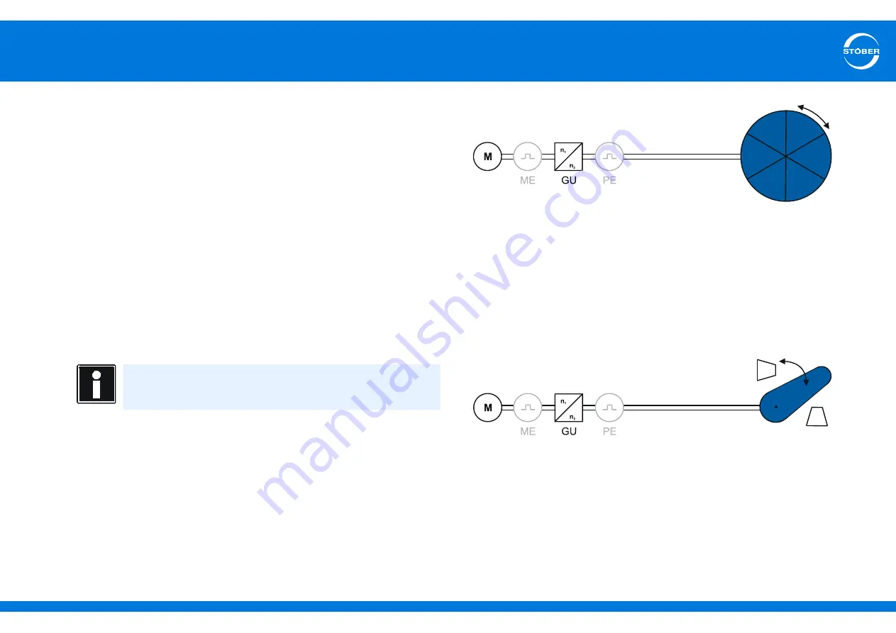
Endless rotary movement
The schematic diagram shows an endless rotary drive using the example of a
motor (M), a gear unit (GU) and a rotary table. The use of encoders is optional.
For endless rotary drives with encoders, the following constellations can be
configured:
•
Rotary motor encoder (ME) = position encoder
•
Rotary motor encoder (ME) and external rotary position encoder (PE)
•
External rotary position encoder (PE) without motor encoder
Limited rotary movement
The schematic diagram shows a limited rotary drive using the example of a
motor (M), a gear unit (GU) and an indicator. The use of encoders is optional.
For limited rotary drives with encoders, the following constellations can be
configured:
•
Rotary motor encoder (ME) = position encoder
•
Rotary motor encoder (ME) and external rotary position encoder (PE)
•
External rotary position encoder (PE) without motor encoder
Information
Note that configurations without motor encoders can only be used
for asynchronous motors.


