IsoAir® 310P
Aerosol Particle Sensor
P/N 1000016128
OPERATIONS MANUAL
Without measurement there is no control
Page 1: ...IsoAir 310P Aerosol Particle Sensor P N 1000016128 OPERATIONS MANUAL Without measurement there is no control ...
Page 2: ...6671 632 E pmsgermany pmeasuring com ITALY T 39 06 9053 0130 E pmssrl pmeasuring com JAPAN T 81 3 5298 8175 E pmsjapan pmeasuring com KOREA T 82 31 286 5790 E pmskorea pmeasuring com MEXICO T 52 55 2271 5106 E pmsmexico pmeasuring com NORDIC T 45 707 028 55 E pmsnordic pmeasuring com PUERTO RICO T 1 787 718 9096 E pmspuertorico pmeasuring com SINGAPORE T 65 6496 0330 E pmssingapore pmeasuring com ...
Page 3: ...ect to change without notice Patent Information The IsoAir 310P particle sensor is protected by the following patents held by Particle Measuring Systems US 6167107 Japan 3559782 Germany 60005581 3 and UK GB1196832 Wireless Radio Designators FCC F4AWLNN551 IC 3913A WLNN551 and Japan Radio Type Certification 208 150044 Quality Statement The Quality Policy of Particle Measuring Systems is to strive t...
Page 4: ...ION A caution in the text is used to highlight an item that if not done or incorrectly done could damage the instrument and or any materials or devices affected by the instrument NOTICE A notice in the text is an instructional communication regarding requirements or policies issued by Particle Measuring Systems NOTE A note in the text is used to highlight an item that is of operational importance ...
Page 5: ...tte Portella 34 00044 Frascati Roma ITALY Distributor s Telephone FAX 39 06 90530130 39 06 9051315 Type of Equipment Particle Sensor Model No IsoAir 310P I the undersigned hereby declare that the equipment specified above conforms to the above Directive s and Standard s Signature Signature Full Name Scott MacLaughlin Full Name Giovanni Scialo Position Director of Engineering Position Vice Presiden...
Page 6: ...ing for Facility Net 3 1 Chapter 4 Facility Net Setup 4 1 Chapter 5 4 20 mA Output Option 5 1 Chapter 6 4 20 mA Input and Solid State Outputs 6 1 Chapter 7 Operations 7 1 Chapter 8 Maintenance 8 1 Chapter 9 Troubleshooting 9 1 Appendix A International Precautions A 1 Appendix B Serial Commands B 1 Appendix C Wi Fi Configuration C 1 Appendix D Modbus D 1 Appendix E OPC Configuration and Operation E...
Page 7: ...vi IsoAir 310P Aerosol Particle Sensor Operations Manual This page is intentionally left blank ...
Page 8: ...ations 1 3 Accessories 1 4 Options 1 4 Chapter 2 Unpacking and Installation 2 1 Unpacking the Sensor 2 1 Shipment Contents 2 1 Not Included 2 1 Sensor Installation 2 2 Selecting a Location 2 3 Effective Sampling Probe Placement 2 3 Setting Up a Remote Sampling System 2 4 Installing the Sensor 2 4 Removing the Electronics Module 2 5 Drilling Holes for Conduit Fittings as needed 2 9 Mounting the Sen...
Page 9: ...ns 4 8 Chapter 5 4 20 mA Output Option 5 1 Configuring 4 20 mA Output 5 1 4 20 mA Out Status Channel Optional 5 2 Status output settings 5 2 2 Channel Mode 5 2 Particle Channel Scale Considerations 5 3 Software Setup for 4 20 mA Output Optional 5 3 Chapter 6 4 20 mA Input and Solid State Outputs 6 1 4 20 mA Input 6 1 Solid State Outputs 6 1 Analog Inputs Connections and Configuration 6 2 Connectio...
Page 10: ... 9 Reset Button C 9 Status LEDs C 10 Tips C 11 Setup Tips and Troubleshooting C 11 Getting Reliable Wireless Networking C 11 Wi Fi Sensor Checklist C 13 WiFi Certificate FCC C 14 WiFi Certificate IoC C 16 Appendix D Modbus D 1 Modbus Overview D 1 Input Registers D 2 Holding Registers D 5 Coils D 6 Data Packet Processing D 7 Associated Values for Specific Registry Entries D 8 Appendix E OPC Configu...
Page 11: ...x IsoAir 310P Aerosol Particle Sensor Operations Manual OPC Server Description E 5 Server Browsing E 5 Appendix F 㦘㹡㒥㦘 䤓䓸德 侯 ...
Page 12: ...13 Figure 2 11 4 20 mA input and solid state output connector 2 14 Figure 2 12 4 20 mA output connector 2 14 Chapter 3 Configuring for Facility Net 3 1 Figure 3 1 Example of the output from the help command 3 5 Figure 3 2 Example of the output from the status command 3 5 Chapter 4 Facility Net Setup 4 1 Figure 4 1 Add Instrument dialog box 4 2 Figure 4 2 IsoAir 310P Configuration dialog box 4 3 Fi...
Page 13: ...reless Network Example C 1 Figure C 2 Configuring an IsoAir 310P from a laptop C 3 Figure C 3 IsoAir 310P Status Command with Wi Fi On C 5 Figure C 4 Wi Fi Card with Ethernet RJ 45 Female Female Adapter for PC C 6 Figure C 5 Wi Fi Bridge Sample Web Page C 7 Figure C 6 Wi Fi Board in IsoAir 310P instrument C 9 Figure C 7 Wi Fi Bridge Rendering Showing Status LEDs C 10 Appendix D Modbus D 1 Appendix...
Page 14: ...ate Outputs 6 1 Table 6 1 Wiring connections for current output sensor 6 2 Table 6 2 Wiring connections for voltage output sensor 6 2 Chapter 7 Operations 7 1 Chapter 8 Maintenance 8 1 Chapter 9 Troubleshooting 9 1 Appendix A International Precautions A 1 Appendix B Serial Commands B 1 Appendix C Wi Fi Configuration C 1 Table C 1 LED Status Descriptions C 10 Table C 2 Wireless Data Rate versus Sig...
Page 15: ...xiv IsoAir 310P Aerosol Particle Sensor Operations Manual Appendix E OPC Configuration and Operation E 1 Table E 1 Data Tags E 2 Appendix F 㦘㹡㒥㦘 䤓䓸德 侯 F 1 ...
Page 16: ...ransducer system Available options include 1 Three 4 20 mA outputs one for fault status and two for particle counts 2 Three 4 20 mA inputs for environmental sensors and 5 solid state outputs for a possible local light control tower to mimic the local LEDs 3 Wireless communication To manage the data the IsoAir 310P particle sensor integrates all data into a single record and sends this record to th...
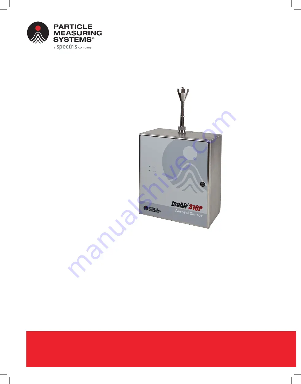
Page 17: ...dicates the operational status of the instrument and is programmable Activity Light The Activity LED flashes when particles are detected Figure 1 1 IsoAir 310P Particle Sensor Top The top of the enclosure contains the sample inlet port Bottom The bottom of the enclosure contains the power and communication connections as well as the exhaust port Power and communications are made through the two fa...
Page 18: ...ed to ISO 21501 4 requirement Zero count level 7 07 counts m3 Maximum particle concentrationa Model 310P 1 374 269 particles ft3 Exterior surface Passivated stainless steel Grade 316 L Communications Particle Measuring Systems protocols via Ethernet data instructions RS 232 instrument configuration and diagnostics only Modbus TCP OPC communications Optional 4 20 mA output 2 data channels plus 1 st...
Page 19: ...aximum Option 3 Wireless communication Wireless communication capability for select countries Fuses 250 V 1 A 5 x 20 mm T Laser classification Class 1 per EN60825 1 Internally a Class 3B laser is used per EN60825 1 Operating environment Temperature 39 95 F 4 35 C Humidity 5 95 non condensing Altitude 0 6 562 ft 0 2000 m Installation requirements Indoor use only Pollution degree 2 Over voltage cate...
Page 20: ...m is undamaged store the packing materials for future transport needs Warranties may not apply if return shipping containers are inadequate Shipment Contents Each IsoAir 310P particle sensor is shipped with the following items IsoAir 310P particle sensor 2 ferrites PMS part number EL136 ISP Isokinetic Sampling Probe with cap and chain Sample tubing 3 meters of Bev a Line 3 8 inch I D Zero count fi...
Page 21: ...nsor on page 2 4 Figure 2 1 is provided as a reference for the installation process This instrument must be installed by qualified personnel and wired by an electrician who is familiar with all applicable electrical codes Install the IsoAir 310P particle sensor on a wall or other vertical surface An external safety disconnect is required To ensure proper and safe operation and to prevent damage to...
Page 22: ...nstalled by qualified personnel The enclosure may be mounted on laboratory structure material such as Unistrut using similar attachment methods as for mounting on a metal framed hollow wall or solid metal sheet wall CAUTION Do NOT mount the instrument to a structure that is not sufficiently strong i e un reinforced sheetrock Cables The unit should be located near a source of grounded electrical po...
Page 23: ...ide To set up an IsoAir 310P for remote sampling 1 Set up a mounting system in the area to be monitored 2 Remove the ISP from the IsoAir 310P enclosure and connect it to the mounting system 3 Insert one end of the Bev a Line tubing through the hole in the top of the IsoAir 310P enclosure and over the particle counter inlet tube 4 Attach the other end of the tube to the bottom of the ISP 5 Adjustth...
Page 24: ...UST be removed from its stainless steel enclosure before attaching the stainless steel enclosure to a wall or other vertical surface NOTE The electronics module should also be removed by qualified personnel from its stainless steel enclosure when performing calibration and some service functions To remove the electronic module 1 Loosen the knurled ring on the top of the box and remove the ISP if p...
Page 25: ...s to the electronics See Figure 2 3 WiFi Power If ordered Electronic Bench Power Blower Do Not Disconnect Ethernet Connection Figure 2 3 Panel Screw Locations 3 Remove the Wi Fi power connector if that option was ordered 4 Remove the bench power connector 5 Remove the Ethernet connection if connected NOTICE DO NOT remove the blower connection ...
Page 26: ...cking and Installation IsoAir 310P Aerosol Particle Sensor Operations Manual Page 2 7 6 Remove the accessory board ribbon cable if options were ordered with this unit Ribbon Cable If ordered Connection Figure 2 4 Accessory ribbon cable ...
Page 27: ...or Installation 7 Loosen the two screws holding the blower in place Figure 2 5 Blower screws 8 Remove the exhaust tubing connected to the zero count filter Exhaust Tubing Disconnect Here Figure 2 6 Exhaust filter 9 Grip the electronic cage and lift slightly up and forward to remove the electronic assembly ...
Page 28: ...rtical surface that is capable of supporting a static load of 80 pounds 36 3 kg It must be installed by qualified personnel Because the electronics module is highly sensitive to electrostatic discharge the electronics module MUST be removed from its stainless steel enclosure before attaching the stainless steel enclosure to a wall or other vertical surface See Removing the Electronics Module on pa...
Page 29: ...g Hole Mounting Hole Mounting Hole Mounting Hole Figure 2 8 Back panel showing mounting holes 4 metal fasteners with a diameter of 1 4 to 3 16 inch For metal studs Expanding metal screws or butterfly bolts For wood studs Minimum of two inches long with self tapping threads suitable for soft material For sheet metal walls a minimum of 1 8 inch thick steel or aluminum Machine screws of 1 4 to 3 16 i...
Page 30: ...wall Drill and tap the wall for the size of fastener that will be used The screws must be long enough to pass completely through the wall material NOTE The sheet metal wall must be a minimum of 1 8 inch thick aluminum or steel Unistrut wall Drill pilot holes for the size of fastener that will be used The fastener scheme between the Unistrut and the wall framing members MUST be equal to or greater ...
Page 31: ... instrument 100 240 V 50 60 Hz 1 A Wires connecting to the AC terminal block must be 14 AWG 2 5 mm2 minimum See Figure 2 10 for wiring placement The terminal block can be removed by loosening its two screws and rotating sliding out of slots The external safety disconnect may be either a switch or a circuit breaker A single or double pole switch is acceptable Figure 2 9 AC Input Wiring Location on ...
Page 32: ... electrical power wiring from the unit or from the facility power connection 2 Turn the fuse holder to remove fuse 3 Replace the blown fuse in the fuse holder with a new fuse as specified above 4 Reinstall the fuse holder 5 Reconnect the power wiring or facility power connection and re apply power Connecting Input Output Cables Wiring should be installed as needed For example if you will not have ...
Page 33: ...14 IsoAir 310P Aerosol Particle Sensor Operations Manual Chapter 2 Unpacking and Installation Sensor Installation Figure 2 11 4 20 mA input and solid state output connector Figure 2 12 4 20 mA output connector ...
Page 34: ...Installation Chapter 2 Unpacking and Installation IsoAir 310P Aerosol Particle Sensor Operations Manual Page 2 15 The analog sensors must be capable of driving a 250 ohm grounded load All grounds are common to the IsoAir 310P particle sensor s internal analog ground The sensor and Facility Net make no assumptions about scale and offset of the 4 20 mA signals Data is sent to Facility Net as raw 4 2...
Page 35: ...Page 2 16 IsoAir 310P Aerosol Particle Sensor Operations Manual Chapter 2 Unpacking and Installation Sensor Installation This page is intentionally left blank ...
Page 36: ...ity Net Setup for information regarding setting up the software for use with the sensor For more information about Facility Net see the Facility Net Users Manual Before You Begin The following are needed in the configuration process Straight through serial cable not a null modem cable with an RJ11 connector A Windows based computer HyperTerminal or other terminal emulation software IP multicast ma...
Page 37: ...o set configuration parameters 1 Using the straight through serial cable connect the computer to the serial port on the IsoAir 310P particle sensor NOTE Do NOT use a null modem cable 2 Start the IsoAir 310P particle sensor 3 Start the computer 4 Start HyperTerminal 5 Use HyperTerminal to set the following parameters Table 3 2 HyperTerminal Configuration Baud 9600 Data Bits 8 Parity N none Stop Bit...
Page 38: ...a bbb ccc ddd Each three digit series is a value of 0 255 separated by a period This address is unique to the hardware it serves For example 224 100 100 001 would be a valid multicast address The value is not saved until the write command is issued set gateway aaa bbb ccc ddd sets the gateway address in decimal notation The gateway address is in the form aaa bbb ccc ddd with each three digit serie...
Page 39: ...erations Manual Chapter 3 Configuring for Facility Net Configuring the Sensor 4 Record the TCP IP setting for future reference Unit Serial Number Date Software Version Set By MAC Address IP Address Multicast Address Net Mask Address Gateway Address ...
Page 40: ...ensor Chapter 3 Configuring for Facility Net IsoAir 310P Aerosol Particle Sensor Operations Manual Page 3 5 Figure 3 1 Example of the output from the help command Figure 3 2 Example of the output from the status command ...
Page 41: ...nnection occurs The samples are transmitted when all the following conditions are met The sensor has already been connected via TCP IP and it has not been reset or power cycled since this connection was made A new socket connection is made to the sensor from the same host as connected before A command to begin sampling is issued via the TCP socket In this and only this situation the IsoAir 310P pa...
Page 42: ... section More detailed information about additional features that enhance data collection and analysis are included in the Facility Net User s Manual Before you begin the IsoAir 310P particle sensor requires that the appropriate TCP IP address multicast address net mask and gateway values be set into the device by means of its RS 232 serial port See Chapter 3 Configuring for Facility Net ...
Page 43: ...nu then Instruments from the drop down menu 2 Click the Add button The Add Instruments dialog box appears Figure 4 1 Add Instrument dialog box 3 Click the Add Network tab in the Add Instrument dialog box 4 Select the applicable IsoAir 310P particle sensor and click the OK button The IsoAir 310P Configuration dialog box appears NOTE If the instrument is not displayed in the sensor list click Poll M...
Page 44: ... be processed as reported by the instrument The volume sampled over time depends on the flow rate The sensor uses this interval when particles are being counted When no particles are counted the Maximum Interval is used This allows for reduced data storage space Maximum Interval If the maximum sample interval is greater than the minimum sample interval zero count reports from individual sensors wi...
Page 45: ...particle sensor To reference the particle channel thresholds 1 On the IsoAir 310P Configuration dialog box click the Channel Configuration tab NOTE This information cannot be changed by the user Figure 4 3 Channel Configuration tab in the IsoAir 310P Configuration dialog box for 4 channel mode When the IsoAir 310P particle sensor is configured for 2 channel mode only two channel sizes will be disp...
Page 46: ...log sensors 1 On the IsoAir 310P Configuration dialog box click the Analog Sensors tab if this option was ordered NOTE Ensure that you use a unique name for the analyzer if multiple analyzers are on the same network 2 In the Name field type a name for each of the Analog Sensors types such as Temperature Pressure 3 Click the OK button in the Instrument Configuration dialog box The sensor status and...
Page 47: ...ld and then added to the number entered into the offset field For a differential pressure with a full scale reading of 0 1 inches of water the correct values to produce a reading between 0 and 0 1 are Scale 0 00625 and Offset 0 025 OK Clicking the OK button accepts the changes to the settings and closes the dialog box Cancel Clicking the Cancel button ignores the changes to the settings if any and...
Page 48: ...ox Field Definitions Status This field displays the operational status of the IsoAir 310P particle sensor Idle Initializing Sampling Communication Error Error This field displays the last detected error message from the instrument Sensor Parameters Values The field below this line displays the current sensor parameters and values Sample Interval Select the hours minutes or seconds units and then u...
Page 49: ...dicates the current operating status of the instrument If the instrument is disabled all other controls are grayed out Disable Allows the user to disable the instrument It also obliquely indicates the current operating status of the instrument If the instrument is disabled all other controls are grayed out Valid Use this data to mark the data subsequently collected as valid This can be used to seg...
Page 50: ...of data output as well as a channel for status Wiring for the output connector is shown in Figure 5 1 CO10 CH 2 CO9 CH 1 CO8 Status Figure 5 1 Wiring for 4 20 mA output There is no need for an additional connector The connector is a push in type that accepts 20 26 AWG wire The connectors shown in Figure 5 1 are from left to right Channel 1 CO9 Channel 2 CO10 Status CO8 ...
Page 51: ...output representingflowandlaserofthecurrentsample willbeheld over from the last sample to allow time for the delayed flow error indication to be processed This will prevent the status 4 20 mA value from jumping between Bad Flow and Good Flow when the counter transitions from one sample to the next 2 Channel Mode The command set instrument 2ch I will set the instrument into 2 channel mode if I 1 or...
Page 52: ...full scale If the recording device is perfect and only sensor errors are seen then the performance will be as follows If a channel is set to 1000 for the scale then the readings will be within 10 counts i e 1 The minimum detectable change is about 2 counts i e 1000 16 mA 0 025 mA or 1 56 In summary setting the scale factor is a balance between setting the scale large enough to cover the worst case...
Page 53: ...w 1 0 Set the 4 20 mA output to raw data output when value 1 Otherwise the data is normalized by the volume in cubic feet set inst auto 1 0 Set to AutoStart when value 1 current I Sets the IsoAir 310P in 4 20 mA output demo mode The instrument generates analog values in order to verify the interface reading Reboot is required to end this mode I current output value NOTE These serial commands are o...
Page 54: ...n in Figure 6 1 Figure 6 1 The 4 20 mA input board Solid State Outputs In addition to the 4 20 mA inputs the same option board can provide 5 solid state outputs These outputs are slaved to the LED status operations Only applicable if Option Board 2 is detected All Digital outputs are shutoff at start up The command set instrument digital I will set the instrument into external digital control mode...
Page 55: ...er and 50 mA maximum current The Analog Inputs can accommodate sensors that output either electrical current e g 4 20 mA or voltage e g 0 10 volts The table below describes the connections for a standard Vaisala Temperature Relative Humidity TRH probe operating with 4 20 mA current outputs Other probes may have different color coding but the connections are the same Table 6 1 Wiring connections fo...
Page 56: ... where Maximum and Minimum is the working Range of the sensor RawData Max and RawData Min is the range of current or voltage The equation simplifies to Scale Sensor s Measurement Range Sensor s Output Range Analog Sensors that Output Current Mostcommonis4 20mAoperation sointerms of 4 20 mA electrical Current the RawData Max is 20 and the RawData Min is 4 Example Using the temperature sensor above ...
Page 57: ...rom previous examples Range 152 measurements from 32 120 F Scale 9 5 if using 4 20 mA current 0 037 if using 0 10 volts Offset Current 32 9 5 4 32 38 70 Voltage 32 0 037 0 32 0 32 Facility Net adjustment of the Scale and Offset values is performed in the Analog Sensors tab during IsoAir 310P instrument configuration Figure 6 2 Facility Net Analog Configuration For the Units column deg C or deg F a...
Page 58: ...ervals When the pump is determined to be working again the system will restart Theattemptedrestartwilloccurfor10times afterthatthesystemwillneedtobereset to begin sampling In addition the blower current is monitored by the electronics to check for over current situations Airflow errors and instrument shutdown conditions are sent to FacilityPro and or Facility Net where they can trigger an alarm De...
Page 59: ...Page 7 2 IsoAir 310P Aerosol Particle Sensor Operations Manual Chapter 7 Operations Detector Board This page is intentionally left blank ...
Page 60: ...terilized by means of liquid spray or mist ideally Turn the pump OFF before capping the sample probe Ingress of liquid or cleaning chemical may damage the internals of the sensor Care must be taken during cleaning processes Calibration Service and Shipping The electronics module is highly sensitive to electrostatic discharge This module has a protective cover to prevent damage When removing for ca...
Page 61: ...Page 8 2 IsoAir 310P Aerosol Particle Sensor Operations Manual Chapter 8 Maintenance Calibration Service and Shipping This page is intentionally left blank ...
Page 62: ...wer Wait at least five minutes Plug AC power back in Do not plug in 24 VDC connector when AC power is on Communications not established Unable to view data from working sensor Unit not initialized correctly Re initialize the unit Ethernet cable problem Replace the Ethernet cable Computer hardware or software problem Substituteacomputerwith known good Ethernet capability Refer to your Computer Ethe...
Page 63: ...Page 9 2 IsoAir 310P Aerosol Particle Sensor Operations Manual Chapter 9 Troubleshooting This page is intentionally left blank ...
Page 64: ...aserprodukt der Klasse 1 welches den Normen US 21 CFR 1040 10 und EN 60825 1 entspricht Das Justieren der Lasereinheit das Verändern des Gerätes oder Einsatzbereiche die nicht den Vorgaben dieser Anleitung für das Gerät entsprechen können dazu führen dass gefährliches Laserlicht austritt ATTENZIONE Lo strumento è classificato come prodotto laser di Classe 1 e rispetta l US 21 CFR 1040 10 e l EN 60...
Page 65: ...Nature of Hazard Attention consult accompanying documents Dangerous High Voltage Warning Laser radiation Avoid exposure to beam Symboles de risque Des symboles représentant les risques sont placés sur l appareil Leur signification est la suivante Symbole Nature du risque Attention consulter les documents d accompagnement Danger Electricite Avertissement Rayonnement laser Éviter toute exposition au...
Page 66: ...en Symbol Gefahrenart Achtung In den beiliegenden Unterlagen nachschlagen Achtung Hochspannung Warnung Laserstrahlung Nicht in den Strahl blicken Simboli di pericolo Il significato dei simboli di pericolo che appaiono sugli strumenti il seguente Simbolo Natura del pericolo Attenzione Consultare i documenti allegati Tensione Pericolosa Avvertenza Radiazione laser Evitare l esposizione ai raggi ...
Page 67: ... International Precautions Simbolos de peligro Simbolos de peligro Los simbolos de peligro que aparecen en el equipo significan Símbolo Naturaleza del Peligro Atención consultar los documentos adjuntos Peligro alto voltaje Advertencia Radiación láser Evite exponerse al rayo ...
Page 68: ...ds or less before the next sample set sam ple x y This command sets the minimum sample interval to x seconds and the maximum sample interval used when zero particles are detected to y seconds PMS strongly recommends that both sample intervals be set to the samevaluewhenconnectedviaOPCinordertodisablethezerocountsample interval processing It is not required to set the sample interval when running t...
Page 69: ...Page B 2 IsoAir 310P Aerosol Particle Sensor Operations Manual Appendix B Serial Commands set inst 2ch 1 0 2 channel mode xxx set inst Auto 1 0 Auto start mode ...
Page 70: ...pendix C Wi Fi Configuration IsoAir 310P Particle Sensors can be configured to communicate with a Wi Fi bridge if ordered with this option Figure C 1 shows an example of a wireless network configuration for IsoAir 310P instruments Figure C 1 Wireless Network Example ...
Page 71: ...from the IsoAir 310P to a laptop that will be needed to configure communications The following items will be required for configuration Laptop with USB to Serial Adapter if laptop does not have a serial port PMS p n 1000005556 HyperTerminal Windows 7 does not include this or a similar program Cat 5 Ethernet Interface Cable RJ 45 to RJ 45 Coupler PMS p n CO713 or 1000005733 Serial Interface Cable P...
Page 72: ...Appendix C Wi Fi Configuration IsoAir 310P Aerosol Particle Sensor Operations Manual Page C 3 Figure C 2 Configuring an IsoAir 310P from a laptop ...
Page 73: ...nfiguration ThestepsforconfiguringtheIsoAir310PintoWi Fimodearedescribedinthefollowing sections Set the IsoAir 310P into Wi Fi mode and select an IP address for the instrument on page C 4 Configure the Wi Fi bridge on page C 6 Set the IsoAir 310P into Wi Fi mode and select an IP address for the instrument NOTE This same IP address will be set in the Wi Fi bridge To set Wi Fi mode and select an IP ...
Page 74: ...ers Analog 1 Scale 1 0000 Offset 0 0000 Analog 2 Scale 1 0000 Offset 0 0000 Analog 3 Scale 1 0000 Offset 0 0000 Digital Outputs internal 0 4 10000 When not connected the led flashes green Data Queue set at 480 Ethernet Connection via PMS Protocol Connected to 010 254 000 102 Aux Board Analog input detected Serial Num 214 Calibrated 11 23 2010 Auto start disabled State Sampling WiFi Default IP Para...
Page 75: ...he Wi Fi card PMS p n 1000013006 can be used as the RJ 45 adapter See Figure C 4 Figure C 4 Wi Fi Card with Ethernet RJ 45 Female Female Adapter for PC 3 In Windows go to the Run menu and type command to open a command window a Type ipconfig to show the network configuration The network configuration should show the following IP Address 192 168 2 100a a The address may be 192 168 2 101 or somethin...
Page 76: ...ac Figure C 5 Wi Fi Bridge Sample Web Page b In the Wi Fi Bridge web page see Figure C 5 click on Configuration c Click on Express Setup to configure the correct IP address d At a minimum the following items numbered 1 5 in Figure C 5 must be configured The WLAN Static IP Address must match the IP address as it is confiured in the IsoAir 310P see Set the IsoAir 310P into Wi Fi mode and select an I...
Page 77: ... WLAN Settings page on the Wi Fi bridge and select the region where you are operating h When all the parameters are set re boot the Wi Fi bridge so the changes will take effect 5 Re attach the RJ 45 connector from the Wi Fi bridge to the sensor s Ethernet connector 6 Verify that the sensor can communicate wirelessly The SSID is the name used to connect to the wireless accesspoint and should be pro...
Page 78: ...in the upper left side of the instrument enclosure see Figure C 6 If option boards are installed in the unit they are placed on top of the Wi Fi bridge Reset button CAUTION Coax is delicate Status LEDs are reflected here Figure C 6 Wi Fi Board in IsoAir 310P instrument Reset Button The Reset button see Figure C 6 will set all parameters back to the factory default The Reset button must be held dow...
Page 79: ...s Figure C 7 Wi Fi Bridge Rendering Showing Status LEDs Table C 1 LED Status Descriptions LED Color Status Power Off No power Red Fail power on self test POST Amber No valid IP address Green OK Link Off No power Blinking Red Searching for Access Point Green OK Associated with Access Point Comm Off No power OR No Wi Fi and no Ethernet connection Red No Wi Fi TCP Physical Ethernet is attached Blinki...
Page 80: ... wireless routers use DHCP by default Do not use DHCP use fixed IP addresses Make sure that the fixed IP range is not being used as part of a range the router uses for DHCP The reason for fixed addresses is that the IP address is used to identify the physical location of the sensor in the system Ensure that the exact same IP address is set in both the Wi Fi bridge and the IsoAir 310P The gateway a...
Page 81: ...mitter and receiver An increase in distance of 1 4x will cause a reduction of 3dBm 802 11b g communications is designed to work reliably with low signal strengths It does this by reducing the communication speed when needed Table C 2 provides a rough idea of signal strength and data rate for 802 11g Table C 2 Wireless Data Rate versus Signal Strength Data Rate 802 11 g Average Signal Strength 54Mb...
Page 82: ... 310P set to Wi Fi mode IP Address set in IsoAir 310P IsoAir 310P re booted with new settings IP Address set in Wi Fi bridge Use the same address as set in the IsoAir 310P in the previous step Net mask set in Wi Fi bridge Gateway set in Wi Fi bridge DNS Server set in Wi Fi bridge SSID set in Wi Fi bridge Security e g WPA WEP 64 set in Wi Fi bridge Correct operating region set in Wi Fi bridge This ...
Page 83: ...Page C 14 IsoAir 310P Aerosol Particle Sensor Operations Manual Appendix C Wi Fi Configuration WiFi Certificate FCC WiFi Certificate FCC ...
Page 84: ...WiFi Certificate FCC Appendix C Wi Fi Configuration IsoAir 310P Aerosol Particle Sensor Operations Manual Page C 15 ...
Page 85: ...Page C 16 IsoAir 310P Aerosol Particle Sensor Operations Manual Appendix C Wi Fi Configuration WiFi Certificate IoC WiFi Certificate IoC ...
Page 86: ...WiFi Certificate IoC Appendix C Wi Fi Configuration IsoAir 310P Aerosol Particle Sensor Operations Manual Page C 17 ...
Page 87: ...Page C 18 IsoAir 310P Aerosol Particle Sensor Operations Manual Appendix C Wi Fi Configuration WiFi Certificate IoC ...
Page 88: ...WiFi Certificate IoC Appendix C Wi Fi Configuration IsoAir 310P Aerosol Particle Sensor Operations Manual Page C 19 ...
Page 89: ...Page C 20 IsoAir 310P Aerosol Particle Sensor Operations Manual Appendix C Wi Fi Configuration WiFi Certificate IoC This page is intentionally left blank ...
Page 90: ... include 1 Read Coils 5 Write Single Coil 15 Write Multiple Coils 4 Read Input Registers 3 Read Holding Registers 6 Write Single Holding Register 16 Write Multiple Holding Registers 23 Read Write Multiple Holding Registers 22 Mask Write Holding Register Any registers accessed but not defined will generate an address error Spare coils registers will set without error and always return a zero value ...
Page 91: ...venience The host can use this to check for data availability for example The Device State register is a single register in which theLSByteisastatevalueandthe MSByte is an associated sub state value The time stamp set of registers is a time_t value The Data Packet Status is two registers 3 bits are used Flow Rate and Volume are in CF These can be read either as integer values with fixed scales or ...
Page 92: ...w nanometers 300 30019 ushort Channel 2 Size high nanometers 30020 ushort Channel 2 Size low nanometers 500 30021 ushort Channel 3 Size high nanometers 30022 ushort Channel 3 Size low nanometers 1000 30023 ushort Channel 4 Size high nanometers 30024 ushort Channel 4 Size low nanometers 5000 Table D 2 Input register Data Packet Input Registers Description Data Packet Comment Notes 30201 ushort Cali...
Page 93: ...30227 ushort Number Particle Channels Variable across types 4 fixed 30228 ushort Number Analog Channels Variable across types 0 or 3 30229 ushort Particle Channel 1 high Cumulative Raw Ch1 30230 ushort Particle Channel 1 low Cumulative Raw Ch1 30231 ushort Particle Channel 2 high Cumulative Raw Ch2 30232 ushort Particle Channel 2 low Cumulative Raw Ch2 30233 ushort Particle Channel 3 high Cumulati...
Page 94: ... sampling The new configuration when completely defined will be run on the next start up The real time clock is set via a time_t value The sample interval and Hold Tare times are single registers for number of seconds to process Note that the Hold Tare time for the IsoAir 310P is the time it will delay between the pump having coming up to specified flow and starting the first sample Table D 3 Hold...
Page 95: ...eger with fixed scaling to a dual register IEEE 754 Float representation This value can also be set into non volatile storage via the setup interface set instrument float n where n 1 on or n 0 off 9 32 Spare Table D 4 Coils Coils Description Coils Comment 00 01 Data Collection On Off Sampling Control 00 02 Data Available Yes No Data Available Queue Control 00 03 Data Clear Toggle Data Queue Delete...
Page 96: ...f of the queue If there is more data in the queue the new data will be shown and the data available coil bit will be set If there is no more data in the queue the data available bit will only be set again once the next sample is completed If the queue is set to one then the data shown is always the last data processed and is representative of real time data only Since the queue is circular the nex...
Page 97: ...tate Entries MSByte Data Packet Status Entries 0x0001 Data Collection Matches the common coil settings 0x0002 Data Available 0x0004 Data Clear 0x0008 Reset 0x0010 Green Status 0x0020 Red Status 0x0040 External Alarm 0x0080 IEEE Float mode 0 Idle 1 Sampling 2 Maintenance 3 Error 0 Idle n a 1 Idle Start pump 2 Idle Pre Sample 0 Sampling n a 1 Sampling Tare 0 Maintenance n a 1 Maintenance Calibration...
Page 98: ...hat arise between OPC clients and servers are due to incorrect DCOM settings Since the IsoAir 310P particle sensor is not a Windows platform you may need to enter a manual registration for the IsoAir 310P OPC server on the computer where the client application will run dependent on the OPC client A Windows registry update file is available Contact Particle Measuring Systems for assistance The IsoA...
Page 99: ... R W Note 3 Digital output 1 Control Output2 VT_I2 None R W Note 3 Digital output 2 Control Output3 VT_I2 None R W Note 3 Digital output 3 Control Output4 VT_I2 None R W Note 3 Digital output 4 Control Output5 VT_I2 None R W Note 3 Digital output 5 Counts CumNorm Ch1 VT_R4 Counts cf R Sample Cumulative data divided by volume Counts CumNorm Ch2 VT_R4 Counts cf R Counts CumNorm Ch3 VT_R4 Counts cf R...
Page 100: ... connection OPC Setup IsoAir 310P OPC provides data via an OPC Server The server supports OPC Data Access Custom Interface Standard 2 05a Information on the OPC specifications and standards can be found at http www opcfoundation org These specifications and standards are essential for understanding how to use OPC Sample FlowRate VT_R4 cf min R Sample flow rate Sample Interval VT_R4 Seconds R Sampl...
Page 101: ... the OPC Foundation The IsoAir 310P OPC was tested with version 2 05A of the data access components Adjustments to the DCOM settings will likely be required for your computer to allow it to read data via OPC We recommend following the settings set forth in the OPC Foundations document Using OPC via DCOM with Microsoft Windows XP SP2 This document is available to download from their website at http...
Page 102: ...ress If the client requires the OPC server to be registered in the local computer s registry settings Particle Measuring Systems can provide you with a registry file with the correct settings The IsoAir 310P OPC identifiers are OPC Server Class ID 0x813f2fd1 0xd2a1 0x4caf 0x97 0x45 0x02 0x32 0x30 0x56 0x00 0x82 OPC Server Program ID ParticleMeasuringSystems xxx AirNet OPC Server Description Partic...
Page 103: ...Page E 6 IsoAir 310P Aerosol Particle Sensor Operations Manual Appendix E OPC Configuration and Operation OPC Server This page is intentionally left blank ...
Page 104: ...ame 捷ↅ 䱿 㦘㹡㒥㦘 䤓䓸德 侯 杔 Pb 㻭 Hg 柘 Cd ↆ杻 Cr VI 䅃勣啾 PBB 䅃勣啾搩 PBDE 䟄䄟 ㄣ X O X O O O Ⓠ䟄恾孔揜 X O X O O O ⷵ ↅ X O X O O O 䉏 X O X O O O 㧉㬿捷ↅ X O X O O O 䟄冕 X O X O O O 㧉䟄 X O X O O O 䟄㻯 X O X O O O O 嫷䯉䞷ℝ捷ↅ䤓㓏㦘 㡞䓸德 㓏 䤓㦘㹡㒥㦘 䓸德 ℝSJ T11363 2006屓 䤓棟 ㄵ尐㻑ᇭ X 嫷䯉䞷ℝ捷ↅ䤓咂 䱜 㡞䓸德 㓏 䤓㦘㹡㒥㦘 䓸德浧ℝSJ T11363 2006屓 䤓棟ㄵ尐㻑ᇭ ...
Page 105: ...Page F 2 IsoAir 310P Aerosol Particle Sensor Operations Manual Appendix F 㦘㹡㒥㦘 䤓䓸德 侯 This page is intentionally left blank ...