


1-50 (E)
BVP-9500WS/9500WSP MM
1-14. Self-Diagnosis
The Diagnosis page of the Operation menu is used for self-diagnosis of every plug-in board.
The Operation menu appears on the viewfinder screen.
Equipment required
Camera adaptor
CA-550/570/950
series
(Use CA-950 series when connecting the CCU-900 series camera control unit.)
Viewfinder
BVF-10/C10W/20W series
Supply power from a camera control unit CCU-550/550P, CCU-700/700P/700A/700AP, CCU-900/900P or
AC adaptor AC-550/550CE.
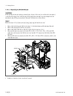
Switches and control knob
Operational procedures
1.
Change the DISPLAY switch from OFF to MENU. The Operation menu is displayed on the view-
finder screen.
2.
Turn the MIC LEVEL control to display the Diagnosis page.
3.
To decide the menu page selection, press the MIC LEVEL control or set the ENTER/CANCEL
switch to ENTER.
4.
The menu page is returned to the previous page every time the ENTER/CANCEL switch is set to
CANCEL.
5.
To cancel the menu operation, set the DISPLAY switch to OFF.
1-14. Self-Diagnosis
VTR
ON
OFF
STBY
OUTPUT
CAM
AUTO
WHITE
WHT
KNEE
SAVE
BARS
M
L
H
A
B
PRE
SET
TESTOUT
ENC
RGB
SEL
SEL
DISPLAY
ON
OFF
MENU
ENTER
CANCEL
GAIN
MIC1 LEVEL control
DISPLAY switch
ENTER/CANCEL switch
Summary of Contents for BVP-9500WS
Page 62: ......
Page 72: ......
Page 206: ......
Page 234: ......
Page 236: ......
Page 246: ......
Page 252: ......
Page 270: ......
Page 277: ......
Page 282: ......
Page 296: ......
Page 322: ......
Page 324: ......
Page 338: ......
Page 340: ......
Page 342: ......
Page 346: ......
Page 350: ......
Page 356: ......
Page 358: ......
Page 360: ......
Page 362: ......
Page 368: ......
Page 372: ......
Page 378: ......
Page 380: ......
Page 382: ......
Page 389: ......


