1-28 (E)
BVP-9500WS/9500WSP MM
1-6. Replacing Function Switches
1-6-1. Side Switch Panel Block/MIC 1 LEVEL Control
c
When opening the side panel during or immediately after use of the unit, be careful as the board panel is
very hot and touching it may result in burns. When opening the side panel to perform inspections and
adjustments, turn off the power and wait 10 minutes for the unit to cool down first.
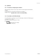
1.
Separate the chassis assembly and base chassis assembly. (Refer to steps 1 to 4 of Section 1-5-1.)
2.
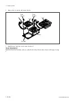
Remove the MIC1 LEVEL control knob.
3.
Open the lid. Remove the four screws, and remove the side switch panel.
4.
Remove the seven cushions.
5.
Remove the shield spring (SW). (For BVP-9500WSP only.)
1-6. Replacing Function Switches
Precision
P2.6
x
8
Precision
P2.6
x
8
Shield spring (SW)
Knob
Lid
Cushions
For BVP-9500 WSP only
Side switch panel
Summary of Contents for BVP-9500WS
Page 62: ......
Page 72: ......
Page 206: ......
Page 234: ......
Page 236: ......
Page 246: ......
Page 252: ......
Page 270: ......
Page 277: ......
Page 282: ......
Page 296: ......
Page 322: ......
Page 324: ......
Page 338: ......
Page 340: ......
Page 342: ......
Page 346: ......
Page 350: ......
Page 356: ......
Page 358: ......
Page 360: ......
Page 362: ......
Page 368: ......
Page 372: ......
Page 378: ......
Page 380: ......
Page 382: ......
Page 389: ......

