7PG2113/4/5/6 Solkor Settings
Section 1: Introduction
1.1
Differential Protection
1.1.1 Protection Sensitivity
Differential Protection sensitivity is fixed, based on secondary current rating, with the only settable variable being
the use of the N/N1 tap. Different sensitivity is applicable to different phases and fault types. Differential
Protection sensitivity is stated in the Performance Specification section of this manual.
1.1.2 Pilot Resistance
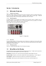
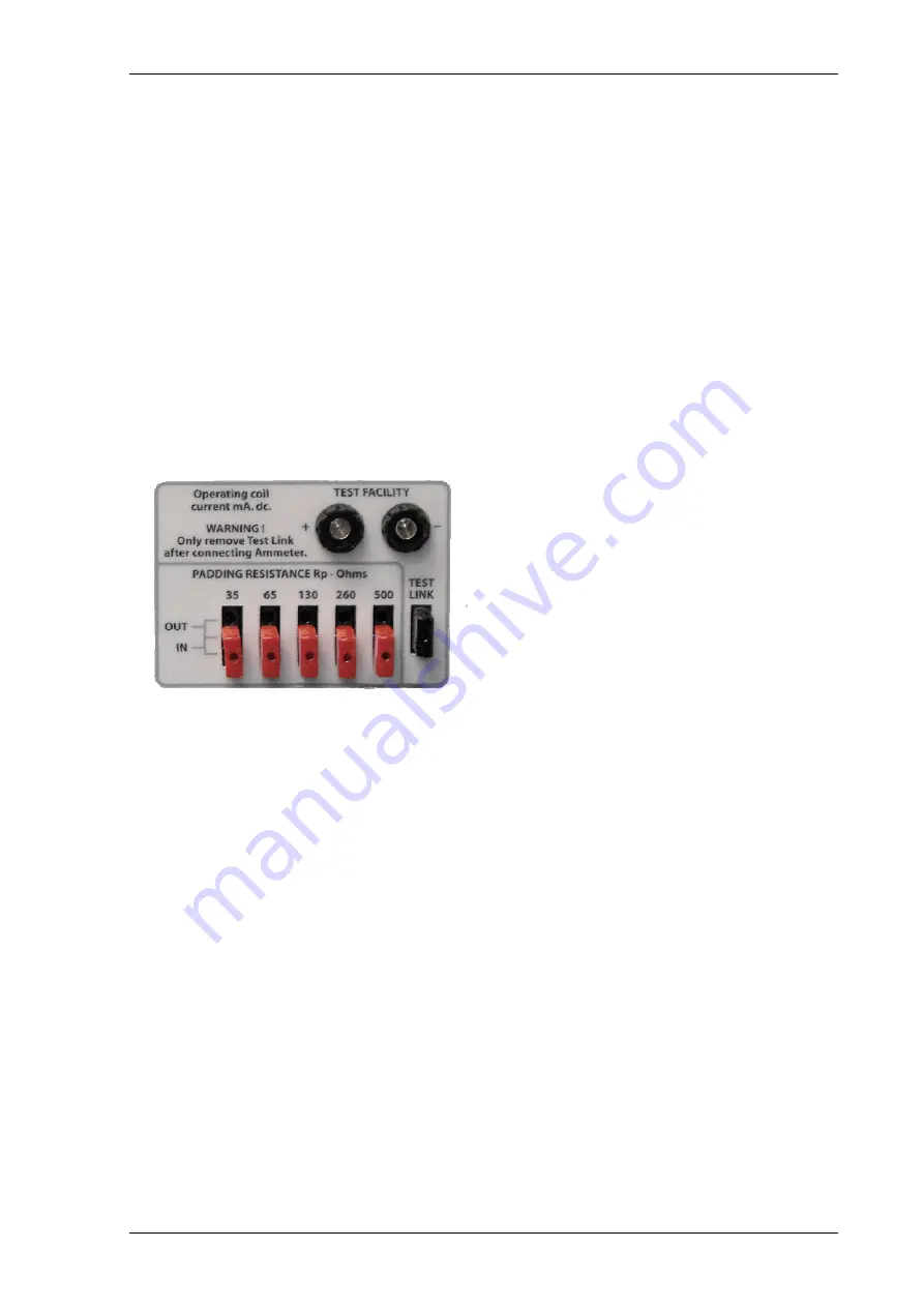
The padding resistance is set by adding series resistance to that of the pilots to achieve a standard value. The
total loop resistance required depend on the R or Rf mode selected and the tap position of the isolation
transformers if they are used, see Applications Guide in this manual.
The link is fitted in the ‘OUT’ position to short out the resistor.
Figure 1.1 -1 Fascia Links
1.1.3 Test Link
The test facility provided on the relay fascia can be shorted by a similar link to that used for Pilot
Resistance settings but black in colour. This link can be removed during testing but should be fitted to
set the relay for normal operation.
1.1.4 Pilot Supervision
There are no variable settings associated with the Pilot Supervision system.
1.2
Relay Menus And Display
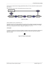
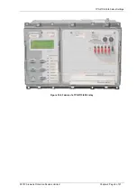
All relay fascias have the same appearance and support the same access keys. The basic menu structure is also
the same in all products and consists of four main menus, these being,
Settings Mode -
allows the user to view and (if allowed via passwords) change settings in the relay.
Instruments Mode -
allows the user to see the conditions that the relay is experiencing i.e. current, voltage etc.
Fault Data Mode -
allows the user to see type and data of any fault that the relay has detected.
Control Mode -
allows the user to control external plant under the relays control for example the CB
©2010 Siemens Protection Devices Limited Chapter 2 Page 3 of 21

