


7PG2113/4/5/6 Solkor Description of Operation
X
D3
Ra
D4
Y
Rp
+
-
D6
D
-
+
W
Z
C
B
A
D5
+
-
-
+
O
P
R
A
B
C
X
Y
W
Z
D
O
P
a
Rp
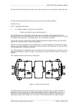
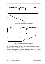
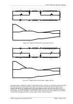
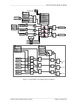
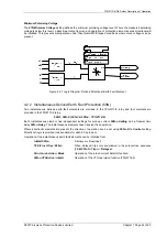
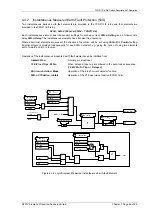
Figure 3.2-9 Internal fault Rf mode, positive half cycle
A
B
C
X
Y
W
Z
D
O
P
B
D7
Ra
D8
C
Rp
+
-
D2
Z
-
+
A
D
Y
X
W
D1
+
-
-
+
O
P
Ra
Rp
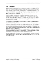
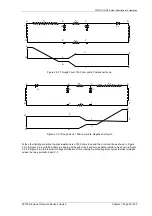
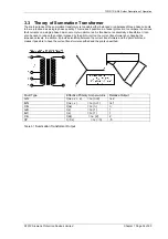
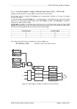
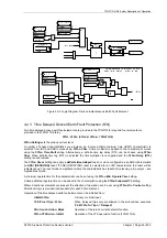
Figure 3.2-10 Internal fault Rf mode, negative half cycle
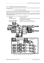
The application of pilot wire protection is generally in interconnected power systems so that it is reasonable to
consider double end fed faults. For simplicity in explaining the basic principles, it may be assumed that the
infeeds at both ends have the same magnitude and relative phase angle. The Solkor Rf circuit is then effectively
as shown in Figure 3.2-9 & Figure 3.2-10 because the diodes in series with the pilots on the positive leg of the
circuit will be out of circuit and the measuring element polarising diodes on this leg will be conducting. The voltage
distribution fore this arrangement shows how, with the assumed balanced infeeds, no current flows in the pilots
and each measuring element is energised via the resistor R
a
.
The single end fed internal fault operates both measuring elements from the one end so that the setting level is
twice that of the double end fed arrangement. However, both ends operate at this level (which is the normal
setting claim) so that the intertripping is not required for internal faults even those which may be fed from one end
or have low infeed at one end
.
©2010 Siemens Protection Devices Limited Chapter 1 Page 32 of 80