7PG2113/4/5/6 Commissioning & Maintenance
©2012 Siemens Protection Devices Limited
Chapter 6 Page 46 of 77
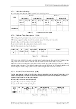
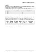
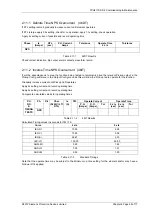
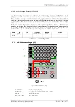
Phase Is
(Amps)
DTL
(sec)
P.U. Current
Amps
Tolerance Operate
Time
2 x Is
Tolerance
REF
Table 2.10-2
64H Results
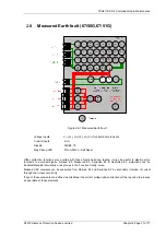
It is also desirable to check the operating voltage achieved with the setting resistor and all parallel CTs connected
but de-energised. A higher capacity test set will be required for this test. Adequate current must be supplied to
provide the magnetising current of all connected CTs. Precautions should be taken to ensure that no personnel
are at risk of contact with any of the energised secondary wiring during the test.
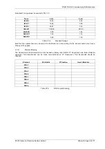
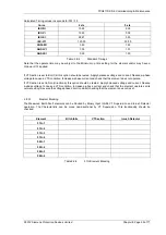
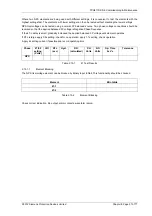
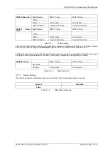
Settings Data Voltage Setting
Measured
Table 2.10-3
64H Operating Voltage
To complete testing of the REF requires primary injection through the phase and residual (REF) CT in series to
simulate an out of zone fault and ensure stability of the relay. The test can then be repeated with the REF CT
secondary connections reversed to prove operation.
2.10.1.1 Element
Blocking
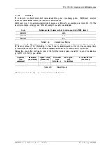
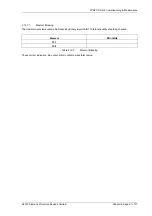
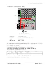
The Restricted Earth Fault element can be blocked by Binary Input Inhibit. This functionality should be checked.
Element BI
Inhibits
64H
Table 2.10-4
64H Inhibit
Check correct indication, trip output, alarm contacts, waveform record.
Check that any shorting links are removed after testing.

