7PG2113/4/5/6 Solkor Description of Operation
For Solkor Rf without isolating transformers the value chosen should be as near as possible to ½(2000-R
p
) ohms.
For Solkor Rf with isolating transformers the value chosen should be as near as possible to
½(SV-R
p
)/T ohms.
where T = Isolating transformer tap.
&
SV = Standard resistance value for tap on transformers,
1780
Ω
for tap1, 880
Ω
for tap 0.5 & 440
Ω
for tap 0.25
The operating element is of the attracted armature type with three contacts, each pair being brought out to
separate terminals. The inherent advantages of such a relay are robustness and simplicity and since the contacts
are suitable for direct operation of a circuit breaker trip coil, no repeat relay is necessary.
A 5kV insulation level is provided between the secondary winding of the summation transformer and its primary
winding. The core and the relay coil is also insulated at 5kV.
Since the only external connections to the relay are those to; the current transformers, the pilots and the tripping
and alarm circuits, the installation and commissioning of the equipment is extremely simple. To check the current
in the operating element, a test point is provided.
The 15kV arrangement is for applications where the voltage across the pilot insulation due to induction or a rise in
station earth potential are excessive and where, consequently, the normal 5kV insulation level is not considered
adequate.
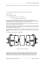
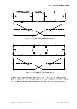
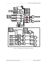
The complete protection scheme is shown in figure below.
Figure 3.1-3 Solkor Rf 15kV schematic
The difference between this circuit and that shown previously is that the pilots are connected via interposing
transformers which incorporate 15kV insulation barriers between windings to isolate the pilot circuit. The
introduction of the isolating transformer does not modify the basic principle of operation of the protection but
allows greater range of pilot coverage by the use of taps on the isolating transformer secondary windings.
©2010 Siemens Protection Devices Limited Chapter 1 Page 26 of 80


