


7PG2113/4/5/6 Solkor Applications Guide
V
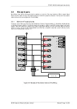
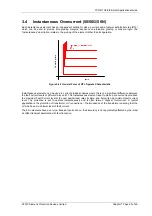
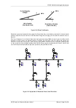
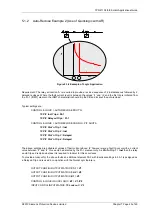
Transformer Feeders
(Cable Circuits)
- 45
0
MTA
Current lagging
Voltage
Plain Feeders
(Overhead Lines)
- 30
0
MTA
I
V
I
Figure 3.5-2 Phase Fault Angles
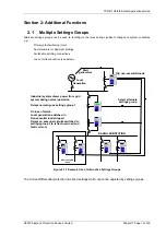
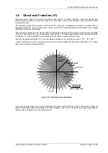
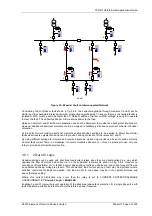
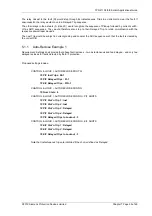
Directional overcurrent elements allow greater fault selectivity than non-directional elements for interconnected
systems where fault current can flow in both directions through the relaying point. Consider the network shown in
fig. 2.6-3.
The Circuit breakers at A, B, E and G have directional overcurrent relays fitted since fault current can flow in both
directions at these points. The forward direction is defined as being away from the busbar and against the
direction of normal load current flow. These forward looking IDMTL elements can have sensitive settings applied
i.e. low current and time multiplier settings. Note that the relays may be programmed with forward, reverse and
non-directional elements simultaneously when required by the protection scheme.
Load
A
C
E
B
D
G
Figure 3.5-3 Application of Directional Overcurrent Protection
©2010 Siemens Protection Devices Limited
Chapter 7 Page 25 of 49