7PG2113/4/5/6 Solkor Applications Guide
1.5
Essential External Wiring and Settings
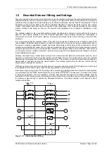
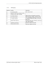
The relay requires external wiring connections to provide the interaction between the electromechanical pilot wire
differential module and the numeric module. This wiring is not fitted at the factory which allows the customer to
customise wiring routing and ferrule marking to suit customer preference and site specific requirements. Current
transformer wiring must be fitted in line with the standard diagrams to connect the Solkor module and numeric
module. Input/output interconnections are required to take advantage of the features provided by the numeric
module. Details of this wiring is shown on the product wiring diagrams and in Chapter 5: Installation, in this
manual.
The settings supplied in the 4 available settings groups are designed to provide a typical scheme for use as a
basis for site specific settings to suit the required application. These settings provide the functionality of
Overcurrent and Earth Fault Guard, Backup Overcurrent and Earth Fault and monitoring of the Pilot Wire
protection.
It is recommended that the tripping contact of the Pilot wire protection is hardwired via a Guard contact to the
circuit breaker. Additional delay caused by routing this signal into a binary input to apply programmable logic in
the numeric module is undesirable. Instead, the simple Guard logic is achieved by series connection of the two
contacts and an additional contact from the pilot wire module should be wired into the numeric module to provide
an alarm signal which is used to provide auxiliary functions. This signal is used to drive indication, raise an event
on the comms protocol , initiate a waveform record and can be used to drive additional repeat contacts and as an
input to additional user logic.
Similarly, the Guard relay contact which is driven from Overcurrent and Earth Fault elements should be set to
operate a contact which is wired in series with the circuit breaker trip coil. This contact can be set to be operated
continuously by energising the Guard Override Binary Input. This contact can also be shorted out externally by a
panel switch to physically remove the Guard function. This method ensures that the CB can still trip with the
Guard relay de-energised or removed.
The Backup Overcurrent and Earth Fault function can provide a separate contact for CB tripping. An inhibit input
is configured for this function also so that the backup protection can be switched off.
Internal user logic is programmed in the settings file to provide trip indication when the Solkor Rf module operates
co-incidentally with the OC/EF Guard. Operation of the Solkor Rf module in the absence of a Guard relay pickup
is indicated separately. This can indicate a problem with the pilot connection but Guard settings must be
considered in this conclusion since this indication will be raised if a low level fault can occur below the settings of
the Guard but high enough to operate the differential protection. Time delay settings can be applied to avoid
nuisance indications.
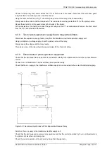
Figure 1.5-1 Interconnection Wiring
©2010 Siemens Protection Devices Limited
Chapter 7 Page 8 of 49

