7PG2113/4/5/6 Commissioning & Maintenance
©2012 Siemens Protection Devices Limited
Chapter 6 Page 76 of 77
a)
Short circuit the pilots and check that the pilot supervision receive relay and its follower relay reset and
that a correct pilot failure alarm is given.
b)
Open circuit the pilots and check that the pilot supervision receive relay and its follower relay reset and
that a correct pilot failure alarm is given.
c)
Reverse the pilots at one end of the feeder and check that the pilot supervision receive relay does not
pick-up and that a correct pilot failure alarm is given. Check that the current recorded by the d.c. milli-ammeter in
the pilots is less than one milli-ampere.
Remove the d.c. milli-ammeter from the pilots and restore all connections to normal.
6.3.10 Stability tests
Check the stability of the protection as described in the appropriate Operating Recommendations.
6.3.11 Putting into service
Make a final check of connections. Ensure that the supervision supply is switched on, that the pilot supervision
receive relay and repeat relay are held operated and that all indications and alarms are reset.
Make the checks described under the heading “Putting into service” in the appropriate Operating
Recommendations.
Finally insert the tripping links.
6.3.12 Notes
17
E
20
V
16
V
19
E
18
E
22
V
E18
C
R
R
C
28 3
26 10
24 4
27 9
240
220
110
E V
Supervision Send End
15kV Vedette or 5kV Epsilon Case
Isloting Transformer
15kV Scheme only
F2
T2
T1
S2
S1
F1
0.5
1.0
0.25
E17
87L
R/Rf Mode
18
V
20
E
14
E
13
E
3
4
8
7
1
2
6
5
Supervision Supply
Fail relay B22
A13/15
A17/19
A21/23
A
25
/2
7
A
B
C
P1
P2
S1 S2
CT
7PG2113/5 Solkor Rf
A
22
/2
4
A
18
/2
0
A
14
/1
6
E
23
E
25
E
27
E
24
A26/28
Pilots to
Remote End
Send Equipment
AC Schematic Diagram
E
26
E
28
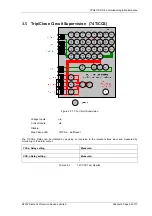
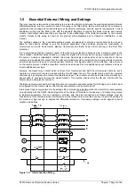
Figure 6.3-2
Pilot Supervision Send Equipment


