7PG2113/4/5/6 Commissioning & Maintenance
©2012 Siemens Protection Devices Limited
Chapter 6 Page 10 of 77
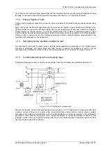
A
B
C
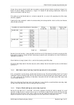
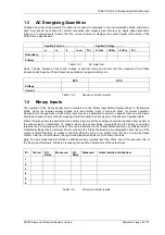
Figure 1.3-2 CT Polarity test 2 arrangement
Connect the test supply to simulate a yellow earth fault as shown in Figure 1.3-2 CT Polarity test 2 arrangement
.
Inject a suitable value of primary current and check the readings on ammeters X and Y. The reading of ammeter
X should equal the reading of the ammeter Y which is connected in the yellow phase C.T. secondary.
Repeat the tests at the other end of the feeder.
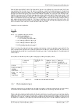
Tabulate the results as shown in Table 1.
Secondary current (A)
Test condition
Primary
current
(amps)
Red
phase
Yellow
phase
Blue
phase
Neutral
phase
Feeder end 1
A-B
B-C
C
only
Feeder end 2
A-B
B-C
C
only
Table 1.3-1
C.T ratio and polarity tests
1.3.5 Pilot Insulation-resistance test
The voltage for the insulation-resistance test of the pilots should not exceed the nominal insulation level of the
pilots, and the test should be made as follows:
With the pilots disconnected from the relay at both ends of the feeder, apply the insulation resistance test
between the pilot cores, and between each core and earth. This test should be carried out with an insulation
resistance test set. Compare the readings obtained with the value quoted by the manufacturer of the pilot-cable.
1.3.6 Pilot-loop resistance tests

