7PG2113/4/5/6 Solkor Description of Operation
Section 3: Current Differential Protection Function
3.1
Description
Conjunctive operation of the Current Differential function and the Overcurrent and Earth Fault Guard functions is
described in the Applications section of this manual.
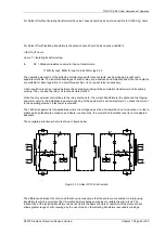
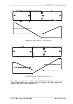
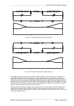
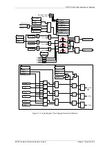
The Solkor Rf protection system (excluding current transformers) is shown below. The alternative basic Solkor R
protection circuit is also shown
.
A
B
C
N
D1
R
D3
D7
D5
R
R
p
a
a
TP
A
B
C
N
D2
R
D4
D8
D6
R
R
p
a
a
TP
N1
N1
Figure 3.1-1 Solkor Rf schematic
Figure 3.1-2 Solkor R schematic
Selection of the Solkor Rf or Solkor R operating mode is arranged by wire links, internal to the relay.
The relay contains an 8-way internal terminal block. 4 wires marked 1-4 must be moved from 4 terminals marked
‘Solkor Rf’ to 4 adjacent terminals marked ‘Solkor R’. Additionally a wire link must be fitted, externally to the relay
on the rear terminal block to use the relay in Solkor R mode.
In addition to the basic components there are at each end, three non-linear resistors, a tapped ‘padding’ resistor
and three diodes. The non-linear resistors are used to limit the voltage appearing across the pilots and the
operating element. The purpose of the ‘padding’ resistors at each end is to bring the total pilot loop resistance up
to a standard value. The protection is therefore always working under constant conditions and its performance is
to a large extent, independent of the resistance of the pilot cable’ The ‘padding’ resistors comprise five series
connected sections, each section having a short circuiting link. The values of the resistance on the sections are
35 ohms, 65 ohms, 130 ohms, 260 ohms and 500ohms.
For Solkor R the value chosen should be as near as possible to ½(1000-R
p
) ohms, where R
p
is the pilot
resistance. The 500 ohm resistor should therefore never be fitted for the Solkor R and the link will always be fitted
for this mode.
©2010 Siemens Protection Devices Limited Chapter 1 Page 25 of 80


