SSCC APPLICATIONS & PROGRAMMING GUIDELINES
_________________________________________________________________________________________________________
4-37
SIG-00-22-02 JUNE 2022 (Revised September 2022)
Version: B.1
Select
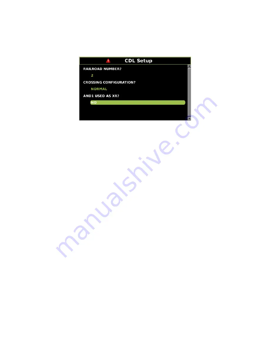
1) Application(CDL) > 1) CDL Setup
. Step through the first group of parameters of
SEAR Programming by answering each question as indicated by the SEAR Program Menu
setup page in the crossing’s circuit plans
Figure 4-19 CDL Setup Screen
4.12.6 SEAR IIi Operation
Now that site setup is complete, peripheral devices, as well as items onboard the SEAR IIi will
be checked for proper operation. This ensures that the SEAR IIi is receiving all the information it
needs for proper alarming and execution of the SEAR Application Program. All items in this
section can be done through similar menus on the GCP5000 (GCE) WebUI.
All peripheral equipment on the Echelon
network will need to be checked for good
communication with the SEAR IIi. All of those modules can be checked on one screen by
scrolling to
IO & Logic View >
4) SEAR
. This opens the SEAR I/O submenus. The submenus
are displayed in the following order when the right arrow is pressed:
•
Digital Inputs 1..16 (includes iLOD and VHF)
•
Digital Inputs 17..32
•
Digital Inputs 33..48
•
Digital Inputs 49..63
•
Analog Input
•
Digital Outputs
•
LEDs
•
MTSS (If installed, otherwise message “No MTSS Data Found in Database!!”
appears)
•
GFT (If installed, otherwise message “No GFT Data Found in Database” appears)
•
SEAR Module Status
The type of module will be shown on the left and the communication status will be on the right.
The status of each module should be “GOOD.”
4.12.7 Verify Operation Of MTSS/Gate Tip/Bell Sensor:
The MTSS can be monitored via the following path:
IO & Logic View >
4) SEAR
then scroll to
the left twice (or right seven times) as per the bulleted menu list in the preceding section. If the
input shows STUCK LOW, then the data wire between the MTSS and SEAR IIi is open and will
need to be repaired.


