3ZW1012-0WL11-0AB1
12 – 2
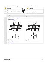
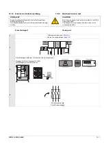
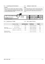
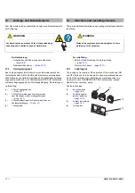
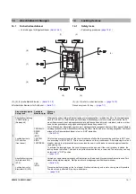
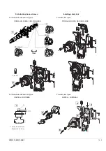
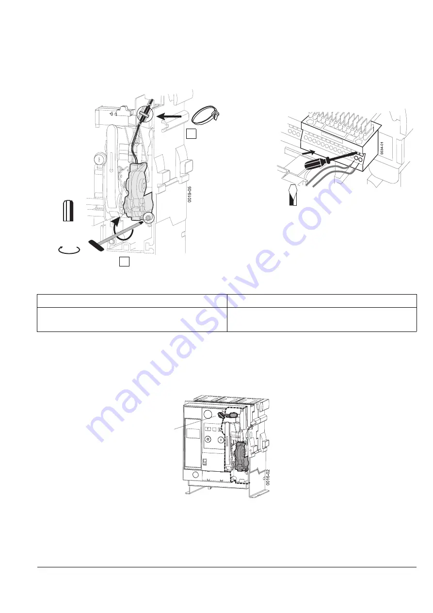
Motorantrieb befestigen /
Leitungen anschließen
→
Schaltpläne
12.2
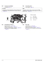
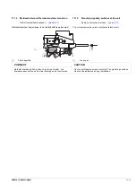
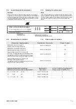
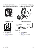
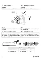
Motorabstellschalter am Bedienpult
Option.
Zum Abschalten der Steuerspannung des Motorantriebs.
Lieferung vorkonfektioniert mit einer angelöteten Leitung.
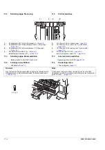
Hinweis
Note
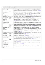
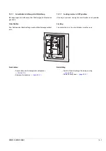
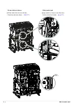
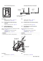
Ggf. fehlende Hilfsstromanschlüsse nachrüsten (Messerleiste,
Hilfsstromstecker, Schleifkontaktmodul für Einschubrahmen).
If necessary missing auxiliary terminals may be retrofitted
(receptacle, auxiliary connectors and sliding contact module for
guide frames).
1
2
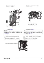
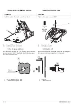
6 Nm
Gr. / Size
5
Nicht möglich bei vorhandenem Elektrisch Ein (S10)
Not possible if Electrical ON (S10) available
Fixing the motor-operated mechanism /
connecting wires
→
Circuit diagrams
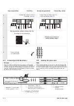
12.2
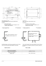
Motor disconnect switch at the front panel
Option.
For de-energizing the motor-operated mechanism.
Supplied pre-assembled with a soldered wire.
3.0 x 0.6
X5
Klemmen / Terminals:
X5.1 (L-) BK / schwarz / black
X5.2 (L+) BN / braun / brown
Summary of Contents for 3ZW1012-0WL11-0AB1
Page 15: ...3ZW1012 0WL11 0AB1 0 XV ...
Page 87: ...3ZW1012 0WL11 0AB1 8 15 S Auslösung I Auslösung S tripping I tripping ...
Page 88: ...8 16 3ZW1012 0WL11 0AB1 Erdschlussauslösung Ground fault tripping ...
Page 359: ...3ZW1012 0WL11 0AB1 27 5 ...
Page 360: ...27 6 3ZW1012 0WL11 0AB1 ...
Page 366: ......
Page 367: ......

