22 – 3
3ZW1012-0WL11-0AB1
22.2
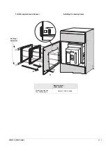
Ausführung mit Kunststoffscharnieren
An der Schaltschranktür mit
drei
Schrauben auf beiden Seiten der
Haube befestigt.
22.2.1
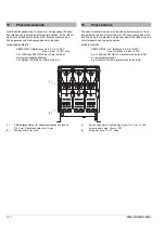
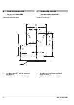
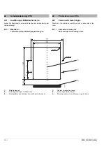
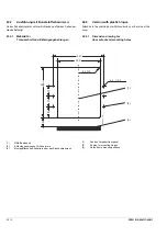
Maßbild für
Türausschnitt und Befestigungsbohrungen
(1)
Mitte Bedienpult
(2)
6 Montagebohrungen für Scharniere
(3)
Montagefläche des Schalters oder des Einschubrahmens
340
70
72
72
68
6 x
Æ
5,5
4 x R 5
341
295
0309-3_mm
(3)
(2)
(1)
22.2
Version with plastic hinges
Attached to the cubicle door with
three
bolts on either side of the
cover
22.2.1
Dimension drawing for
door cutout and mounting holes
(1)
Centre of breaker front panel
(2)
6 holes for mounting hinges
(3)
Guide frame mounting surface
Summary of Contents for 3ZW1012-0WL11-0AB1
Page 15: ...3ZW1012 0WL11 0AB1 0 XV ...
Page 87: ...3ZW1012 0WL11 0AB1 8 15 S Auslösung I Auslösung S tripping I tripping ...
Page 88: ...8 16 3ZW1012 0WL11 0AB1 Erdschlussauslösung Ground fault tripping ...
Page 359: ...3ZW1012 0WL11 0AB1 27 5 ...
Page 360: ...27 6 3ZW1012 0WL11 0AB1 ...
Page 366: ......
Page 367: ......

