10 – 6
3ZW1012-0WL11-0AB1
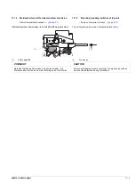
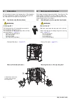
10.8
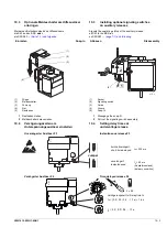
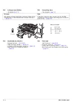
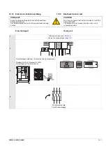
Connecting wires
→
Circuit diagrams
10.9
Final work
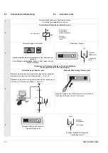
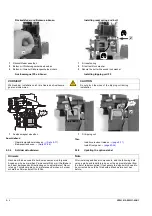
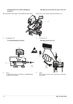
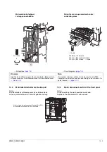
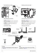
- Install front panel
- Fit auxiliary connectors
- Connect wires to auxiliary connector
→
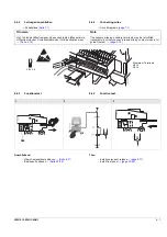
- Move the draw-out circuit breaker into the test position
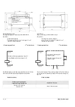
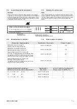
Y1
F1
F2, F3
F4
: X6.7 / X6.8
: X6.13 / X6.14
: X5.11 / X5.12
: X5.11 ... X5.14
: X7.9 / X6.7
S10
Klemmen / Terminals:
10.8
Leitungen anschließen
→
Schaltpläne
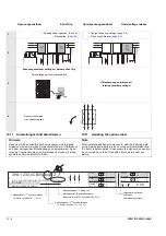
10.9
Abschließende Arbeiten
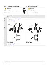
- Bedienpult anbauen
- Hilfsstromstecker aufsetzen
- Leitungen an Hilfsstromstecker anschließen
→
- Einschubschalter in Prüfstellung verfahren
Hinweis
Note
Ggf. fehlende Hilfsstromanschlüsse nachrüsten (Messerleiste,
Hilfsstromstecker, Schleifkontaktmodul für Einschubrahmen).
→
If necessary missing auxiliary terminals may be retrofitted
(receptacle, auxiliary connectors and sliding contact module for
guide frames).
→
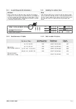
3.0 x 0.6
Summary of Contents for 3ZW1012-0WL11-0AB1
Page 15: ...3ZW1012 0WL11 0AB1 0 XV ...
Page 87: ...3ZW1012 0WL11 0AB1 8 15 S Auslösung I Auslösung S tripping I tripping ...
Page 88: ...8 16 3ZW1012 0WL11 0AB1 Erdschlussauslösung Ground fault tripping ...
Page 359: ...3ZW1012 0WL11 0AB1 27 5 ...
Page 360: ...27 6 3ZW1012 0WL11 0AB1 ...
Page 366: ......
Page 367: ......

