8 – 130
3ZW1012-0WL11-0AB1
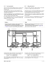
8.5.5
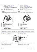
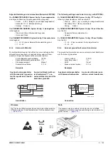
Bedienung
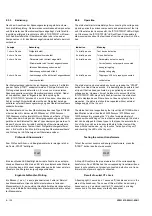
Nach dem Anschluss der Spannungsversorgung startet automa-
tisch die Statusprüfung. Dabei werden verschiedene Komponenten
und Parameter des Überstromauslösers abgefragt. Verlief die Sta-
tusprüfung erfolgreich, leuchtet die LED „ETU STATUS“ mit Dauer-
licht. Anderenfalls ist der Überstromauslöser oder eine seiner
Komponenten (z. B. das Bemessungstrommodul) defekt oder nicht
vorhanden.
Der Statustest kann jederzeit durch längeres (mehr als 3 s) Betäti-
gen der Taste „START“ wiederholt werden. Prinzipiell ist auch die
Prüfung eines bereits aktivierten, z. B. eines von einer externen
Spannungsquelle versorgten Überstromauslösers möglich. Dabei
ist zu beachten, dass im Ergebnis der Statusprüfung die
LED „ETU STATUS“ durchaus 2 x kurz blinken kann, ohne dass ein
Fehler vorliegt. Sicherheitshalber sollte der Statustest bei abge-
schalteter externer Spannungsversorgung des Überstromauslösers
wiederholt werden.
Der Statustest wird von den Überstromauslöser des Typs ETU25B
mit einer Ident-Nr. kleiner als 253030xxxxxx / 273030xxxxxx /
150704xxxxxx nicht unterstützt. Durch Drücken der Taste „L“ für ca.
3 Sekunden beim Anlegen der Versorgungsspannung an das Prüf-
gerät kann der Statustest für diese Typen übersprungen werden. In
diesem Fall muss die korrekte Funktion des Überstromauslösers
vor dem Start weiterer Tests mit dem Prüfgerät sichergestellt wer-
den, z. B. durch die Funktion „Aktivierung des Überstromauslösers“
und Prüfung der LED-Anzeigen am Überstromauslöser.
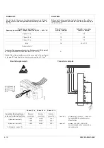
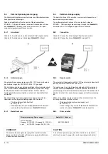
Prüfen der Stromwandler
Zum Prüfen der Strom- und Energiewandler kurz (weniger als 2 s)
die Taste „START“ betätigen.
Eine leuchtende LED bestätigt die korrekte Funktion des entspre-
chenden Wandlers. Blinkt eine LED, ist der entsprechende Wandler
nicht vorhanden, nicht korrekt angeschlossen, defekt oder es ist ein
Wandler ohne Energieversorgung angeschlossen.
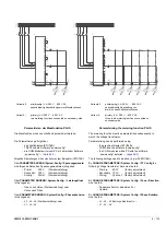
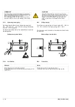
Ergebnis N-Wandler-Prüfung
Ein Blinken (1 s an, 1 s aus) signalisiert einen Fehler im Bereich
des Messwandlers. Ursache dafür ist entweder ein fehlender
Messwandler (z. B. kein externer Neutralleiter-Wandler angeschlos-
sen), eine fehlerhafte Verbindung zum Messwandler oder ein defek-
ter Messwandler.
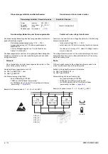
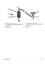
Anzeige
Bedeutung
1 x kurz, Pause
Prüfgerät defekt
2 x kurz, Pause
Überstromauslösers defekt
4 x kurz, Pause
- Parameter nicht korrekt eingestellt
- Stromwandler nicht korrekt angeschlossen
- falsches Bemessungsstrommodul
- Bemessungsstrommodul fehlt
5 x kurz, Pause
- Auslösemagnet F5 nicht korrekt angeschlossen
- Auslöser defekt
START
8.5.5
Operation
The status test starts immediately after connecting the voltage sup-
ply and queries the various components and parameters of the trip
unit. If the status test is successful, the “ETU STATUS” LED will light
up. Otherwise, the “ETU STATUS” LED will flash. It is possible to
draw conclusions about the fault cause from the way in which it flas-
hes.
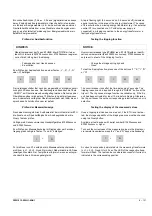
The status test can be repeated any time by pressing the “START”
button for at least three seconds. It is basically also possible to test
a trip unit that is already activated, e.g. supplied by an external
voltage source. However, it must be taken into account that the
“ETU STATUS” LED may briefly flash twice when the status test
result is displayed even if there have not been any faults. As a
precaution, the status test should be repeated without external
voltage supply of the trip unit.
The status test is not supported by the trip unit type ETU25B with an
identification number less than 253030xxxxxx / 273030xxxxxx /
150704xxxxxx. By pressing the “L” button for approximately 3
seconds while switching on the test device power supply, the status
test can be skipped for these types. In that case the accurate func-
tion of the trip unit has to be ensured before further tests will be
done with the test device, e.g. by function “Activation of trip unit”
and checking the LED on the trip unit.
Testing the current transformers
To test the current sensors and energy transformers, press the
“START” button less than two seconds.
A lit-up LED confirms the proper operation of the corresponding
transformer. If an LED flashes, the corresponding transformer/trans-
ducer is not available, not properly connected, defective or a trans-
former without power supply is connected.
Result of neutral CT check
A flashing light (1 second on, 1 second off) indicates an error in the
area of the transducer. The cause of this will either be a missing
transducer (e.g. no external neutral CT connected), a missing
connection to the transducer or a faulty transducer.
Indication
Meaning
1 x briefly, pause
Test device defective
2 x briefly, pause
Trip unit defective
4 x briefly, pause
- Parameters not set correctly
- Current sensor not properly connected
- wrong rating plug
- Missing rating plug
5 x briefly, pause
- Tripping coil F5 not properly connected
- coil defective
START
Summary of Contents for 3ZW1012-0WL11-0AB1
Page 15: ...3ZW1012 0WL11 0AB1 0 XV ...
Page 87: ...3ZW1012 0WL11 0AB1 8 15 S Auslösung I Auslösung S tripping I tripping ...
Page 88: ...8 16 3ZW1012 0WL11 0AB1 Erdschlussauslösung Ground fault tripping ...
Page 359: ...3ZW1012 0WL11 0AB1 27 5 ...
Page 360: ...27 6 3ZW1012 0WL11 0AB1 ...
Page 366: ......
Page 367: ......


