3ZW1012-0WL11-0AB1
20 – 2
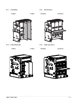
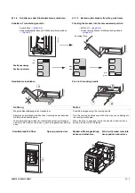
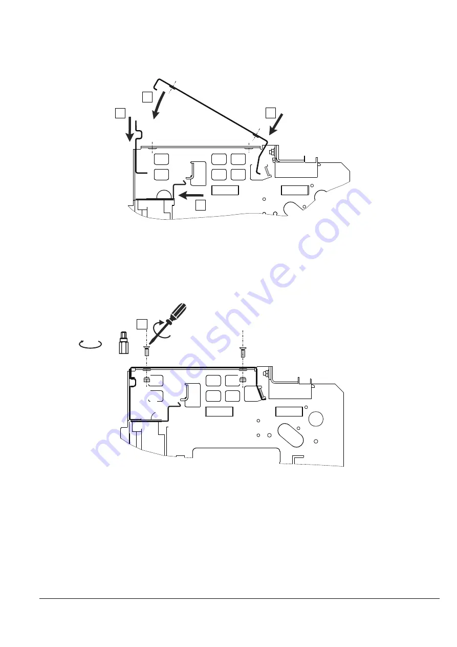
20.1.1
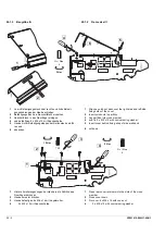
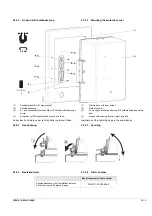
Baugröße I und II
1
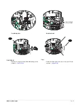
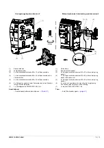
Abschottblech auf Kunststoffrückwand auflegen und Kon-
touren ineinander ausrichten.
2
„Haube hinten“ einsetzen
3
„Haube oben“ hinter Befestigungslappen der Seitenwände
einführen und
4
auf den Einschubrahmen auflegen
1) Abbildung kann vom Original abweichen
1
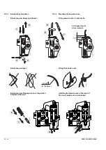
„Haube oben“ befestigen:4 x M6 x 16 mit Kegelmutter
0202-1-1b
1
4
3
2
1)
0202-1-2b
1
T 30
12 Nm
20.1.1
Frame size I and II
1
Insert partition on plastic back and adjust the contours to
each other.
2
Insert "rear cover"
3
Insert "upper cover" behind fixing strap of side walls
and
4
lay on guide frame
1) Image may differ from original
1
Fixing „upper cover":4 x M6 x 16 with cone nut
Summary of Contents for 3ZW1012-0WL11-0AB1
Page 15: ...3ZW1012 0WL11 0AB1 0 XV ...
Page 87: ...3ZW1012 0WL11 0AB1 8 15 S Auslösung I Auslösung S tripping I tripping ...
Page 88: ...8 16 3ZW1012 0WL11 0AB1 Erdschlussauslösung Ground fault tripping ...
Page 359: ...3ZW1012 0WL11 0AB1 27 5 ...
Page 360: ...27 6 3ZW1012 0WL11 0AB1 ...
Page 366: ......
Page 367: ......


