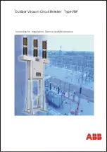
background image

Outdoor Vacuum Circuit Breaker   Type VBF

Instruction for Installation, Service and Maintenance 

Summary of Contents for VBF Series

Page 1: ...Outdoor Vacuum Circuit Breaker Type VBF Instruction for Installation Service and Maintenance ...

Page 2: ...on Installation Commissioning Periodical checks PART C Operating Mechanism working principle and Maintenance Spring charged mechanism Maintenance of operating mechanism Failure Report List Of Drawings Drawings Dismantling of operating coil setup 3 5 6 8 9 11 12 13 13 13 27 30 33 34 39 42 46 47 55 Check that the personnel operating the apparatus have this instruction manual with them We recommend t...

Page 3: ...h each other as well as to the operating mechanism with a linkage arrangement Simple design minimises spare parts 1 Top terminal 2 Arc chamber insulator 3 Vacuum interrupter 4 Bottom terminal 5 Insulating rod 6 Support insulator 7 Bottom crank housing Description Medium Voltage circuit breaker type VBF with operating mechanism type ESH 1 1 Design of the circuit breaker 1 Pole assembly The circuit ...

Page 4: ... simple and robust spring operated mechanism is used Features O C O operation without recharging Closing spring is charged by motor in less than 15 secs Mechanical electrical anti pumping Provision for manual charging Suitable for high speed auto reclosing Manual closing and tripping arrangement Mechanical ON OFF and SPRING CHARGED indication Auxiliary switch 13 NO 13 NC Additional tripping soleno...

Page 5: ...Goods marking 1 2 Documents 1 3 Transport 1 4 Lifting 2 0 Receipt storage prior to installation 2 1 General 2 2 Receipt storage of breaker 3 0 Safety provisions and assembly instructions 3 1 Warning texts 3 2 Safety Precaution PART A Receipt Storage Safety ...

Page 6: ...y Each case is marked with case markings on two sides with indelible black ink The case markings include information of case number gross weight etc In addition to the above the cases are marked with the following symbols These should be observed when choosing lifting equipment 1 2 Documents Following documents are packed with breaker Instruction manual Test certificates Drawings Packing list This...

Page 7: ... not be stacked one over the other Lifted by a lifting device equipped with forks or slings If a crane is used slings shall be used The units must not be rolled or dropped 1 4 Lifting Before lifting the case observe the information on it such as symbol weight etc The cases shall be Lifting the case PART A Receipt Storage Safety Duct with pole Cabinet Structure Loose structure optional 1500 2110 26...

Page 8: ...s Abnormality if any must be notified immediately to ABB forwarding agents and the insurance company The operating cabinet should be unpacked on arrival If it is not going to be stored in an approved storage the heating elements must be connected permanently to the electric supply to protect the control equipment from corrosion or freezing damage The breaker with duct poles should be stored in the...

Page 9: ...indicates an immediate risk situation that can lead to death or serious personal injury if not avoided Warning indicates a risk situation that can lead to death or serious personal injury if not avoided Caution indicates a risk situation that can lead to small or moderate damage Note is used when there is danger that can lead to equipment damage only Important indicates an operation or a suggestio...

Page 10: ... plate is placed on the supporting frame No work must be carried out unless the closing and opening springs are discharged the circuit breaker is in position OFF 0 and the supply to the motor is disconnected The operating mechanism must not be operated unless it is connected to the circuit Work close to the insulators of the circuit breaker that entails risk of porcelain damage must not be carried...

Page 11: ...t with poles on cabinet 4 2 1 6 Assembly of entire circuit breaker on structure 4 2 2 Installation of breaker with cabinet at lower height 4 2 2 1 Various parts of structure assembly 4 2 2 2 Unpacking of structure 4 2 2 3 Assembly sequence for structure 4 2 2 4 Unpacking of duct pole assembly 4 2 2 5 Dismantling of cases 4 2 2 5 1 Unpacking of cabinet 4 2 3 High voltage connections 4 2 4 Low volta...

Page 12: ...ated normal current Rated breaking capacity 26 3kA 24 for 24kV 36 for 36kV 12 for 1250 Amp 16 for 1600 Amp 1 2 Specifications 1 3 Rating plate Type VBF 36 Standard IEC 62271 100 Rated voltage 36kV Frequency 50 Hz Insulation level 70 170kVp Normal current 1250 1600 Amps Short circuit breaking current 26 3 kA Operating sequence 0 0 3S CO 3 Min CO Weight 800 kg PART B Installation Operation Maintenan...

Page 13: ...r mechanically through Breaker Pole The breaker pole consists of ref Fig 2 10001 Insulator body 10200 Vacuum interrupter 10017 Lamellar contact 10502 Current collecting hub 10008 10500 Upper and lower terminal 10300 Insulating Rod 10401 Crank Housing The poles are filled with SF6 or Nitrogen gas individually at a pressure of 1 5 bar abs Nitrogen can be provided on request push button arrangement T...

Page 14: ... included in the delivery Check the packing list Check that no parts have been damaged during transport especially the porcelain insulators Report any faults immediately to the ABB representative Before delivery both Tripping and Closing Springs are discharged and Circuit Breaker kept in OPEN position Before starting installation ensure that foundation with Foundation Bolts as per drawing is ready...

Page 15: ...e Assembly Now fix Cross Support Angles 5 as shown using M12 bolts spring washers plain washers Hex Nus Slide Upper Leg Assembly 1 into Lower Leg Assembly to Fix Support Angles 3 as per the order bound GA drawing For the sake of flexibility do not fully tighten the fasteners 1 3 5 and M12 bolts spring washers plain washers Hex Nuts PART B Installation Operation Maintenance Fix the Lower Leg Assemb...

Page 16: ...port Angles 9 For the sake of flexibility do not fully tighten the fasteners 1 9 1 9 10 7 11 1 1 Shown Circuit breaker Structure Assembly with CT structure 4 2 1 4 Dismantling of Cases 4 2 1 4 1 Unpacking of Cabinet Cabinet Assembly on palate Remove top all side covers of casing containing Cabinet Do not remove the bottom pallet Assembly Remove Vacuum sealing PART B Installation Operation Maintena...

Page 17: ... with Duct assembly Remove Vacuum sealing as shown Duct open the rear cover and place it slowly on the cabinet Assemble Duct with Cabinet using M12 bolts Remove Bolts from bottom after assembly of Duct Cabinet is over 4 2 1 5 Assembly of Duct with Poles on Cabinet Assembly of Poles with Duct Cabinet Assemble Poles with Duct Cabinet together Remove the bolts from the pallet as shown the Cabinet Lif...

Page 18: ...nsure that stiffener plates are placed inside the duct and assemble with structure Engage Cabinet with the support angles Fix M12 bolts spring washers plain washers from bottom of the support angles M12 Nuts are welded inside the cabinet This completes the assembly Now fasten all hardware do not remove slings until all hardware are fastened fully Fixing the Breaker on the structure Fix Cabinet wit...

Page 19: ...r arm Rotate the Composite Lever such that the hole of the lever arm matches with the hole in Driving Link insert the pin Insert the Pin from back and put U Clip This completes the assembly Now fasten all the hardware Remove the lifting ropes wooden blocks Carry out pre commissioning tests as Described in Commissioning section Sequence 1 Sequence 2 Sequence 3 ...

Page 20: ...setting Cover for driver link Top support angle Before starting installation ensure that foundation with Foundation Bolts as per drawing is ready Refer Fig 1a 1b 1c on page 47 48 49 4 2 2 1 Various parts of Structure assembly List of the parts of structure 1 Upper Leg Assly 2 Nos 2 Lower Legs Assly 2Nos 3 Top Support Angles front and rear 2 Nos 5 Stiffeners 2Nos 6 Cross Angles 4 Nos 7 Foundation B...

Page 21: ...ture Arrangement without CT structure Fix the Lower Leg Assly as shown in Fig 4 Fix M20 Plain Washer Spring Washer Hex nut or Expansion Bolts in case the foundation is with Keep Nuts slightly loose for flexibility during entire Expansion bolts Assembly of structure Check that no parts have been damaged during transport especially the porcelain insulators Report any faults immediately to the ABB re...

Page 22: ...ts 2 Fix 2 nos eye bolts on the cabinet diagonally remove fixing bolts 2 and lift the cabinet 4 2 2 4 Unpacking of Duct Pole Assembly Remove top all side covers of casing containing Hold Poles with Duct Assembly by lifting crane as Remove the M8 Bolts from the rear covers of the Remove bolts fixed to the bottom packing pallet Poles with Duct assembly Remove Vacuum sealing as shown Duct open the re...

Page 23: ...e Upper Leg 7 in Lower Leg assembly assemble using Fix Support Angles 9 on Upper Leg Assembly 1 7 as M12 bolts spring washers plain washers Hex Nuts For the sake of flexibility do not fully tighten the fasteners Fix CT Frame 10 on the Support Angles 9 Fix Cross Angles 11 Shown Circuit breaker Structure Assembly with CT structure 8 11 12 5 9 10 1 Fix the cabinet on the lower support angles such tha...

Page 24: ...24 PART B Installation Operation Maintenance Lift the pole and duct assembly and fit it on the structure as shown in figure Put stiffener plate inside the duct where duct upper legs are bolted together ...

Page 25: ... Caution Do not attempt to close the circuit breaker before drive link setting is over View from rear angle with notch removed for clarity Gaskets Tighten all fasteners of the structure Fix pipe assembly for driver link as shown in figure 2 nos gaskets one at top and one at bottom of pipe assembly are to be used Add remove gaskets to adjust the height of the pipe assembly Insert a drive link throu...

Page 26: ...e made as shown in GA drawing Fig 3 pg 51 All earthing joints should be securely bolted together Connections to the station earthing should have a cross section not less then that of the earth connection pad welded on the structure Charge the closing spring operate the breaker 3 to 4 times Check the breaker open position setting once again if it has changed reset again Tighten the nuts on drive li...

Page 27: ...d in any case insulation resistance between phases constant in time and exposed conductive part of the circuit Auxiliary circuits The insulation resistance should be a With a 500 V Megger measure the few Mohm and in any case constant insulation resistance between the in time auxiliary circuits and the exposed conductive part Auxiliary Check that the connections to the The connections are according...

Page 28: ...Attempt closing takes place the circuit breaker closing operation Insert the key again and turn it 90 deg Both electric and manual Carry out the closing operation closing take place correctly in this position the key cannot be removed Changeover Put the changeover switch on REMOTE The operations and signals switch for Close the operating mechanism are normal Local Remote enclosure door Carry out a...

Page 29: ...ng device Issue a close command by applying a control voltage to terminal 101 102 leave the voltage applied The breaker will close Issue open command by applying a voltage to terminal 103 104 The breaker will open After the interruption by OPEN command the circuit breaker should not re close in spite of the CLOSE command still being present Note The ESH operating mechanism on VBF circuit breaker i...

Page 30: ...first check On the basis of the results obtained during the periodic inspections contact an ABB service center for any clarifications Before carrying out any operation make sure that the operating mechanism springs are discharged and that the apparatus is in the open position Maintenance operation Carry out the general inspection For details refer clause 7 4 Measure the insulation resistance Lubri...

Page 31: ...nuts or screws Their position and tighten the nuts screws High voltage Presence of dust or dirt on the Clean with a dry brush or breaker pole the insulating parts cloth parts Locking rings out of place Re fix the locking rings in loose nuts or screws Their position and tighten the nuts screws Distortion or cracking of the Ask ABB Nasik for insulating parts replacement of the damaged parts Trace of...

Page 32: ...upply voltage of The close opening coils circuit supply the operating mechanism must operate correctly for voltage electrical accessories values between 85 and 110 of the relative rated voltage Operating and Carry out the functional tests Replace the damaged or control faulty elements if elements necessary as ABB 32 Part Abnormalities noticed Remedies subjected to PART B Installation Operation Mai...

Page 33: ...ng principle 1 3 1 Electrical spring charging 1 3 2 Manual spring charging 1 4 Breaker Operation 1 4 1 Closing operation 1 4 2 Tripping operation 1 5 Maintenance of Operating Mechanism 1 5 1 Maintenance Schedule 1 5 2 Trouble shooting guide 1 5 3 Replacement of operating coils 1 5 4 Replacement of micro switch 1 5 5 Replacement of motor 1 5 6 Replacement of operating mechanism 1 5 7 Recommended sp...

Page 34: ...s charged or not and the number of opening operations are recorded by the counter The motor can be supplied via station battery a network or via transformer with a limit load of at least 500 VA The motor starts after each closing operation and charges the closing springs within 15 seconds 1 2 Construction The construction of the operating mechanism is shown in Fig A Major components of ESH mechani...

Page 35: ...ing gets stretched 1 3 Operating mechanism Working principle There are two options for charging the springs 1 By electric motor 2 Manual operation and this continues till the spring gets fully charged The backward rotation of the charging gear 2 is prevented by latches 4 A plastic cam activates Motor cut off switch Spring Charged indication will appear after full charging Closing lever 6 stops the...

Page 36: ...rther since the charging gear has no teeth on remaining periphery 1 4 1 Closing Operation Consider both the springs are in discharged condition and breaker is open Ref Fig E Page 37 In this condition neither close nor open operation is possible to perform on the breaker Latch assembly La and Lb are in released condition The closing spring can be charged either electrically or manually as explained...

Page 37: ... La Lb Lever Half Shaft Closing lever Charging Shaft P1 Power Shaft Tripping Cam Assembly Tripping Lever CLOSING COMMAND Mechanism Lever Latch TRIPPING SPRING Fig G Circuit Breaker Closed tripping spring charged Fig E Mechanism in open condition both the springs in discharged condition Fig F Mechanism in open condition Closing Springs is charged PART C Operating Mechanism working principle mainten...

Page 38: ...ection Downward movement of latch assembly will release the latch Lb Hence there is no more pressure or any engagement that will retain the current poison of arm and leverage Armand leverages are free to move now As previously discussed these components are directly connected to charging shaft Tripping spring directly exerts pressure on the shaft via tripping lever As leverage becomes free to move...

Page 39: ...sembly for proper open close operation 8 Checking of setting Proper engagement of lever on shaft 9 Spring cut off micro switches 10 Lubrication of charging device and operating gear NOTE 1 Complete overhaul of circuit breaker operating mechanism to be done after 10000 operation or 10 years whichever is earlier 2 Ask ABB Nasik for details of overhaul procedure 1 5 2 Trouble shooting guide FAULT CAU...

Page 40: ...angement for micro switch 1 5 5 Replacement of motor Refer Figs 10 to 12 page no 57 59 indicate the mounting arrangement for motor 1 5 6 Replacement of operating mechanism The operating mechanism shall be replaced in the following manner a Disconnect the linkage of the operating mechanism to the main shall be replaced in the following manner b Disconnect the electrical connection c Loosen screws t...

Page 41: ...1 Spring charging motor 15032 2 Tripping closing coils 15030 A B 3 Micro switches 15033 4 Auxiliary switches 15027 5 Shock absorber 15007 6 Operating box assembly 15012 7 Opening transmission lever 15010 8 Closing transmission lever 15011 9 Operating Mechanism 15000A 41 PART C Operating Mechanism working principle maintenance ...

Page 42: ... and operating mechanism 1 Identification Date Customer Item designation Serial number Order number 2 Historical data Condition of the breaker when the failure was detected only one alternative to be selected In service During maintenance During installation Use of the circuit breaker Only one alternative to be selected Line breaker Reactor breaker Capacitor breaker Transformer breaker By pass bre...

Page 43: ...rona Loose parts Missing parts Faulty parts Corrosion Surface defect other then corrosion Incorrect function Change in functional characteristics Incorrect closing time Incorrect opening time coil I Incorrect opening time coil II Incorrect damping Incorrect CLOSE OPEN time Too high resistance Incorrect pre insertion time for the resistors Incorrect time span between contacts 4 External circumstanc...

Page 44: ...net Auxiliary contact Counter Control panel Limit switch Micro switch Thermal relay or heater Terminal blocks cables Driving motor for mechanism OPERATING MECHANISM UNIT ESH mechanism Different Assemblies in ESH Mechanism Opening coil set up Closing coil set up Tripping spring assembly Electric motor Auxiliary switch Indicators Counter Opening breaker indicator Closing breaker indicator Latch asse...

Page 45: ... explosion Removal from service of other breakers to prevent repetition of failure Circuit breaker downtime Beyond planned time hours 7 Action taken Select only one alternative Repair of defective component Exchange of defective component Exchange of circuit breaker pole Exchange of operating device Exchange of circuit breaker Action to be taken Select only one alternative By personnel from ABB By...

Page 46: ...reaker control cabinet at lower height with breaker structure 4a b c ESH mechanism with cabinet 5 Dismantling of operating coils setup 6 Steps for replacement of shunt opening release Y02 7 Steps for replacement of shunt opening release Y01 8 Steps for replacement of shunt closing release YC 9 Operating Coils setup for temperature 10 C 10 11 Steps for replacement of motor 12 Motor 13 14 Steps for ...

Page 47: ...sed steel structure Ms Control cubicle with spring drive VCTs CT Supporting structure Galvanised steel structure Ge Earthing point Galvenising Bus Vi Supporting insulator column Fb Foundation bolt M20 Aa Terminals Al alloy Fl Interrupting chamber 47 Drawings Fig 1a Standard General Arrangement Drawing of VBF Breaker with breaker CT structure Note Mounting holes for mounting of CT on CT Structure a...

Page 48: ...colour Brown Cs Position indicatior ON OFF Mech Counter Vs Supporting structure Galvanised steel structure Ms Control cubicle with spring drive VCTs CT Supporting structure Galvanised steel structure Ge Earthing point Galvenising Bus Vi Supporting insulator column Fb Foundation bolt M20 Aa Terminals Al alloy Fl Interrupting chamber Note Mounting holes for mounting of CT on CT Structure are 450 X 4...

Page 49: ...dicatior ON OFF Mech Counter Vs Supporting structure Galvanised steel structure Ms Control cubicle with spring drive Ge Earthing point Galvenising Bus Vi Supporting insulator column Fb Foundation bolt M20 Aa Terminals Al alloy Fl Interrupting chamber Fig 1c Standard General Arrangement Drawing of VBF breaker control cabinet at lower height with breaker structure ...

Page 50: ... Breaker Pole Assembly Part No Description 10001 Insulator body 10200 Vacuum interrupter 10017 Lamellar contact 10502 Current collecting hub 10008 10500 Upper and lower terminal 10300 Insulating Rod 10401 Crank Housing ...

Page 51: ...FIG 3 TYPICAL SCHEMATIC DIAGRAM FOR VBF36 51 Drawings ...

Page 52: ...52 Drawings Fig 4a ESH Mechanism with Cabinet Refer Legend on pg 54 Fig 4b ESH Mechanism with Cabinet Refer Legend on pg 54 ...

Page 53: ...53 Drawings Fig 4c View from Rear side Covers removed ...

Page 54: ...ng 15012 Operation Box Assembly 15013 Push button For Closing 15014 Push button For Opening 15015 Opening Breaker Indicator 15016 Posterior Plate Assembly 15017 Column For fixing Shield 15018 Bending Spring 15019 Hook Assembly 15020 Hook Support Shaft 15021 Intermediate Plate 15022 Front Plate 15023 Power Shaft 15024 Bearing Spacer 15025 Bearing 15026 Charging Shaft 15027 Auxiliary Switch 15028 Co...

Page 55: ...nt of the operating mechanism For assembly proceed in the reverse order Fig 6 FOR ASSEMBLY PROCEED IN REVERSE ORDER YO2 SHUNT OPENING RELEASE Unscrew the four coil fixing screws 14 and withdraw the relative YC coil 15 Unscrew the four coil fixing screws 19 and withdraw the relative YO1 coil 18 Steps for replacement of shunt opening release Yo2 ...

Page 56: ...O1 SHUNT OPENING RELEASE When the YC shunt closing release is present unscrew the four fixing screws 14 and withdraw it 15 Unscrew the four fixing screws 17 and withdraw the relative YO1 release 16 Disconnect the power supply connectors of the additional shunt opening release Fig 8 YC SHUNT CLOSING RELEASES Unscrew the four fixing screws and withdraw release 8 FOR ASSEMBLY PROCEED IN REVERSE ORDER...

Page 57: ...pawls and push the lever towards 4 4 Unscrew the motor flange fixing screws 6 6 Raise the pair of driving latches using screwdriver and push the lever 3 forward 3 Remove the two motor limit microswitch fixing screws 2 Fig 10 Steps For Replacement of Shunt Opening Release YO2 15030 Operating Coil Set Up for Temperature 10 deg C Fig 9 ...

Page 58: ...58 Dismantling of Operating Coils Setup Disconnect the motor power supply 7 Fig 11 Fig 12 Motor ...

Page 59: ...nt of micro switch 15033 For assembly connect the Faston as it was in its original position Unscrew the microswitch fixing screws Fig 13 Unscrew the microswitch fixing screws 2 2 Disconnect the microswitch connection 4 4 3 Pull down cover of microswitch 3 To assemble proceed in reverse order Fig 14 ...

Page 60: ...26186000 Fax 91 11 26197592 84035 www abb com in 1VDU28003 YN Jan 05 4th Floor No 9 Lala Lajpat Rai Sarani Elgin Road Kolkata 700 020 Tel 91 33 22832911 906 Fax 91 33 22832990 ABB House Dr S B Path Ballard Estate Mumbai 400 038 Tel 91 22 56318231 39 Fax 91 22 56318276 77 Vandana House 1st Floor G E Road Ramkund Raipur 492 001 Tel 91 771 5060816 18 Fax 91 771 5023051 Embassy Star 1st Floor No 8 Pal...

Reviews: