3ZW1012-0WL11-0AB1
23 – 2
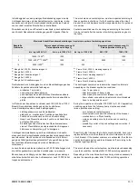
The arc chutes and contact system must be inspected according to
these operation instructions. If a fault condition opens the circuit
breaker, the circuit breaker should be inspected before it is put back
into service.
Contact assemblies need to be changed according to their condi-
tion, but at least after the number of switching operations given in
the table.
a)
Frame Size I, 2000 A, breaking capacity H
b)
Frame Size II, 3200 A
c)
Frame Size II, breaking capacity C
d)
Frame Size II, 4000 A
e)
Frame Size III, breaking capacity C
The switchgear operator has to determine inspection intervals
depending on the breaker application conditions:
- min. 1 x per annum
- after interruption of heavy loads
- after trips by the overcurrent release (trip unit)
- down stream connected non-automatic circuit breakers
have to be inspected as well
During the inspection and/or after 1000 (500 for 1150 V application)
switching operations, the following items must be examined:
(max. operations see catalog)
- arc chutes and contact systems
- electrical and mechanical functionality of the breaker
- mechanical on- / off-functionality
- main and auxiliary circuits, function and connecting
quality
- plausibility control of trip unit settings and correction, if
necessary
Draw-Out guide frames with arc-chute covers installed, have to be
replaced after no more than three short-circuit interruptions of the
circuit breaker. If the breaker endurance is exhausted, then the bre-
aker and old spare parts need to be disposed off, according to the
effective legal regulations.
The arc chutes and the contact system must be replaced depending
upon their condition, but latest after 10,000 switching operations.
Depending on the circuit breaker stress it may also be necessary to
replace the operating system after 10,000 switching operations.
In Abhängigkeit von den jeweiligen Betriebsbedingungen sind die
Lichtbogenkammern und das Kontaktsystem zu inspizieren. Insbe-
sondere nach erfolgter Kurzschlussabschaltung ist deren Zustand
noch vor dem erneuten Einschalten zu kontrollieren.
Strombahnen sind je nach Zustand zu wechseln, jedoch spätestens
nach Anzahl Nennstromabschaltungen gemäß folgender Tabelle.
Der Betreiber hat in Abhängigkeit von den Einsatzbedingungen des
Schalters Inspektionsintervalle festzulegen:
- mindestes 1 x pro Jahr
- nach schweren Abschaltungen
- nach Auslösen des elektronischen Überstromauslösers
- nachgeschaltete Leistungstrennschalter sind ebenfalls zu
prüfen
Im Rahmen der Inspektionen und/oder nach 1000 (500 bei 1150 V-
Einsatz) Nennstromabschaltungen sind zu kontrollieren:
(max. Schaltspiele entsprechend Katalogangaben)
- Lichtbogenkammern und Kontaktsystem
- elektrische u. mechanische Funktionen des Schalters
- Funktion der mechanischen Ein- und Ausschaltung
- Haupt- und Steuerstromkreise, Funktion und Anschlüsse
auf festen Sitz prüfen
- Einstellungen des elektronischen Überstromauslösers
sind auf Plausibilität und entsprechend den Anlagenver-
hältnissen zu überprüfen, ggf. zu korrigieren
Lichtbogenkammerabdeckung am Einschubrahmen sind späte-
stens nach drei Kurzschlussabschaltungen des Leistungsschalters
auszutauschen. Nach Erreichen der Lebensdauer ist die Entsor-
gung des Schaltgerätes/ ausgetauschter Teile gemäß den gelten-
den rechtlichen Bestimmungen durch den Betreiber zu
veranlassen.
Je nach Zustand, spätestens jedoch nach 10 000 Schaltungen sind
die Lichtbogenkammern und das Kontaktsystem zu erneuern.
Ebenso kann es abhängig von der Beanspruchung des Leistungs-
schalters erforderlich sein, das Antriebssystem nach 10 000 Schal-
tungen auszutauschen.
Maximale Anzahl Nennstromabschaltungen / maximum number of switching operations
Baugröße
Frame size
Bemessungsbetriebsspannung U
e
Rated operational voltage U
e
Bemessungsbetriebsspannung U
e
Rated operational voltage U
e
bis / up to 690 V AC
bis / up to 1000 V AC
bis / up to 1150 V AC
600 V DC
1000 V DC
I
10000 / 7500
a)
a)
Baugröße I, 2000 A, Schaltvermögen H
1000
--
--
1000
II
7500 / 4000
b)
c)
/ 2000
d)
b)
Baugröße II, 3200 A
c)
Baugröße II, Schaltvermögen C
d)
Baugröße II, 4000 A
1000
500
6000
1000
III
2000 / 1000
e)
e)
Baugröße III, Schaltvermögen C
1000
500
--
--
Summary of Contents for 3ZW1012-0WL11-0AB1
Page 15: ...3ZW1012 0WL11 0AB1 0 XV ...
Page 87: ...3ZW1012 0WL11 0AB1 8 15 S Auslösung I Auslösung S tripping I tripping ...
Page 88: ...8 16 3ZW1012 0WL11 0AB1 Erdschlussauslösung Ground fault tripping ...
Page 359: ...3ZW1012 0WL11 0AB1 27 5 ...
Page 360: ...27 6 3ZW1012 0WL11 0AB1 ...
Page 366: ......
Page 367: ......

