3ZW1012-0WL11-0AB1
26 – 3
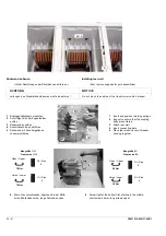
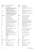
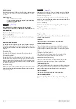
Gegenseitige mechanische Verriegelung
Ermöglicht verschiedene Varianten der gegenseitigen Verriegelung
von Leistungsschaltern.
Hilfsauslöser
Es stehen Unterspannungsauslöser und Spannungsauslöser
(= Arbeitsstromauslöser) zur Verfügung.
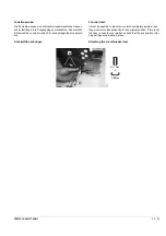
Kodierung Handstecker
Um ein Vertauschen der Hilfsleiteranschlüsse zu verhindern wurden
die Handstecker kodierbar gestaltet.
Lamellenkontakte
Verbinden die Hauptanschlüsse des Leistungsschalters mit den
Hauptanschlüssen des Einschubrahmens.
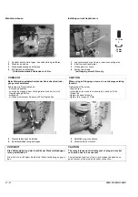
Mechanische Wiedereinschaltsperre
Nach einer Überstromauslösung ist der Schalter gegen Wiederein-
schalten gesperrt, bis die mechanische Wiedereinschaltsperre von
Hand zurückgesetzt wird.
Meldeschalter Schaltstellung
Die Betätigung dieser Hilfsstromschalter erfolgt in Abhängigkeit
vom Schaltzustand des Leistungsschalters.
Motorantrieb
Durch den Motorantrieb wird der Federspeicher automatisch
gespannt, sobald Spannung an den Hilfsstromanschlüssen anliegt.
Nach einer Einschaltung wird der Federspeicherantrieb automa-
tisch für die nächste Einschaltung gespannt.
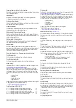
Nennstromkodierung
→
Bemessungsstromkodierung
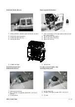
Positionsanzeige
Zur Anzeige der Schalterposition im Einschubrahmen
Positionsmeldeschalter
Zur Fernanzeige der Schalterposition im Einschubrahmen
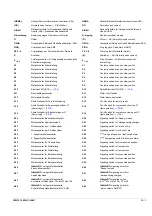
Powerconfig
Inbetriebnahme- und Service Software, kostenlos verfügbar unter:
www.siemens.com/powerconfig-download
powerconfig
(ab Version 2.2) dient als gemeinsames Inbetrieb-
nahme- und Wartungs-Werkzeug für die kommunikationsfähigen
Leistungsschalter. Es bietet eine einheitliche Oberfläche und ein
einheitliches Bedienkonzept bei den durchzuführenden Aktivitäten
wie
- parametrieren
- bedienen
- beobachten sowie
- diagnostizieren.
Aktuell unterstützt
powerconfig
die Sprachen Deutsch und Englisch.
s. „SENTRON Kommunikationshandbuch“
→
http://support.automation.siemens.com
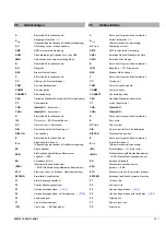
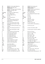
Schaltvermögen (IEC 60947-2)
N
= Leistungsschalter mit ECO-Schaltvermögen
= 2
S
= Leistungsschalter mit Standardschaltvermögen
= 3
H
= Leistungsschalter mit hohem Schaltvermögen
= 4
C
= Leistungsschalter mit sehr hohem Schaltvermögen
= 5
DC = Leistungsschalter mit DC-Schaltvermögen
= 8
Powerconfig
Software for commissioning and service, free of charge available at:
www.siemens.com/powerconfig-download
powerconfig
(from Version 2.2) is used as a shared commissioning
and maintenance tool for the circuit breakers with communication
capability. It
offers a standardized interface and a uniform operator
control concept for the activities to be carried out, such as
- Parameterizing
- Operating
- Monitoring, and
- Diagnosing.
powerconfig
currently supports German and English.
“SENTRON communication handbook”
→
http://support.automation.siemens.com
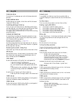
Rated current coding
→
The rated current is coded at the factory, i.e. each and every circuit
breaker can only be inserted in a guide frame with the same rated
current.
Rating Plug
This module defines e.g. the setting range of the overload protec-
tion.
Remote reset
The electrical signal of the triped signaling switch and the red reset
button are reset by the optional remote reset magnet.
Safe OFF
This additional function prevents closing the circuit breaker and ful-
fils the disconnecting condition in OFF position as per IEC 60947-2:
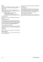
- "Mechanical Off" button pressed
- main contacts open
- crank handle of draw-out circuit breakers removed
- the various interlocking conditions are fulfilled.
Shunt trip
For remote circuit breaker tripping and locking against closing
Shutter
Shutters are insulation plates for covering live main circuits in the
guide frame (shock protection).
Signaling switch for switch position
These auxiliary switches operate according to the circuit breaker
switch position.
Spring charging lever
The spring storage is charged manually by several pumping opera-
tions.
Spring storage
Module containing a spring as an energy store. The spring is char-
ged by means of a hand-operated lever or a motor, and is latched in
its charged state. When the latches are released, the stored energy
is transmitted to the pole, the circuit breaker closes.
Tool operation
A cover with a hole (
∅
6,35) means that buttons can only be pres-
sed using a rod.
Trip signaling switch
Summary of Contents for 3ZW1012-0WL11-0AB1
Page 15: ...3ZW1012 0WL11 0AB1 0 XV ...
Page 87: ...3ZW1012 0WL11 0AB1 8 15 S Auslösung I Auslösung S tripping I tripping ...
Page 88: ...8 16 3ZW1012 0WL11 0AB1 Erdschlussauslösung Ground fault tripping ...
Page 359: ...3ZW1012 0WL11 0AB1 27 5 ...
Page 360: ...27 6 3ZW1012 0WL11 0AB1 ...
Page 366: ......
Page 367: ......


