11 – 2
3ZW1012-0WL11-0AB1
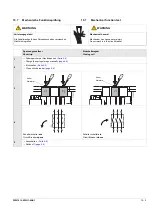
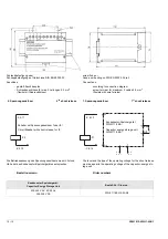
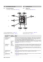
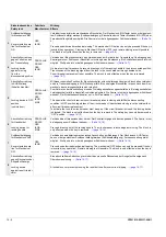
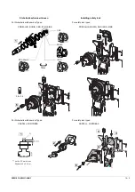
Meldeschalter Schalterstellung
Die Anschlussleitungen der Meldeschalter sind an die Hilfsleiter-
klemmblöcke X5 und X6 entsprechend dem Verdrahtungsplan
→
anzuklemmen.
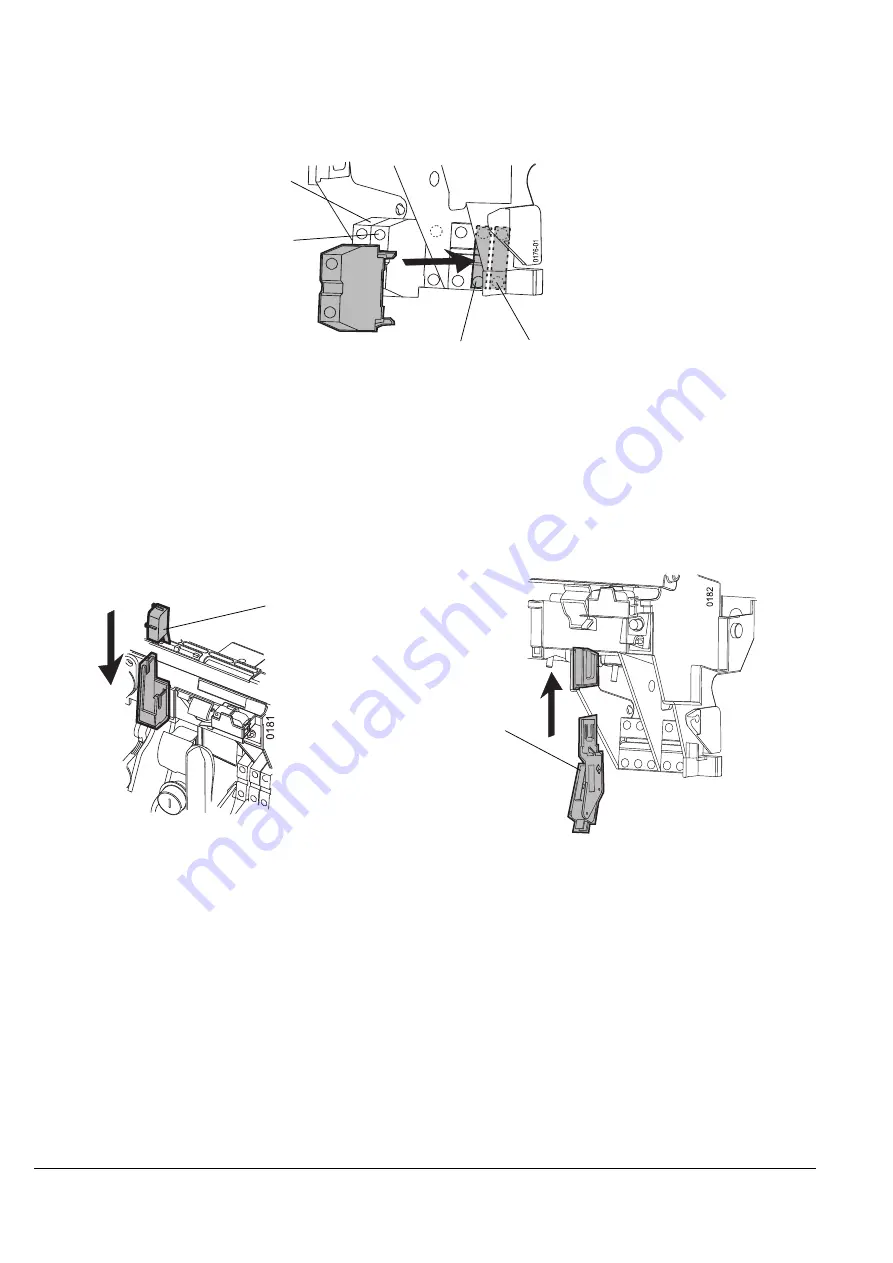
Die Anschlussleitungen der Meldeschalter sind an den Klemmblock
S20 an X6, S21 an X7 entsprechend Verdrahtungsplan
→
anzuschließen.
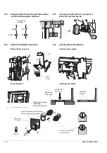
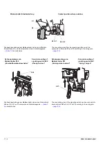
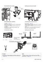
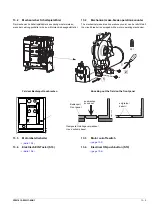
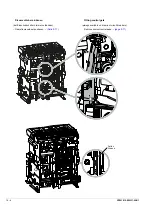
Schnappmontage von
Meldeschalter S20
„Einschaltbereitmeldeschalter“
Schnappmontage von
Meldeschalter S21
„Federspeicherzustand“
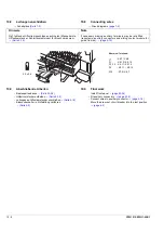
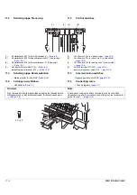
S1
S2
S3 / S7
S4 / S8
S20
Contact position-driven switches
The connecting wires from the signaling switches must be
connected to terminals X5 and X6 according to the wiring plan
→
.
The connecting wires of the signaling switch must be connected to
terminal block S20 at X6, S21 at X7 according to the wiring plan
→
.
Snap in mounting of
signaling switch S20
„Ready-to-close”
Snap in mounting of
signaling switch S21
“spring charged”
S21
Summary of Contents for 3ZW1012-0WL11-0AB1
Page 15: ...3ZW1012 0WL11 0AB1 0 XV ...
Page 87: ...3ZW1012 0WL11 0AB1 8 15 S Auslösung I Auslösung S tripping I tripping ...
Page 88: ...8 16 3ZW1012 0WL11 0AB1 Erdschlussauslösung Ground fault tripping ...
Page 359: ...3ZW1012 0WL11 0AB1 27 5 ...
Page 360: ...27 6 3ZW1012 0WL11 0AB1 ...
Page 366: ......
Page 367: ......


