background image

 1

Elektrische Einschaltverriegelung

3WX3152-1J.00

Electrical closing lock-out

3WX3152-2JA00

Zubehör Magnet / Accessories magnet
Zubehör Leitungsverlegung mit Hilfsschalter / Accessories cabling with auxiliary switch

Alle Rechte vorbehalten. All rights reserved.
© Siemens AG 1988

3WN1, 3WS1

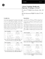
Fig. 1 Auslöserplatte mit elektrischer Einschaltverriegelung F4 (5b)

Release plate with electrical closing lockout F4 (5b)

5b

Betriebsanleitung/Operating Instructions

Bestell-Nr./Order No.: 3ZX1812-0WX31-5EN0 / 9239 9535 174

Warnung!

Gefährliche Spannung!

Gefährlicher Federspeicher!

Vor Beginn der Arbeiten Gerät spannungsfrei schalten
und gegen Wiedereinschalten sichern.
Nur bei ausgeschaltetem Schalter und entspanntem
Federspeicher arbeiten.
Bei  Nichtbeachtung  können  Tod, schwere Körperver-
letzung oder erheblicher Sachschaden die Folge  sein.
Einbau und Montage nur durch Fachpersonal!

Hazardous voltage!

Hazardous spring pressure

Before beginning work on the unit, switch it to a de-
energized state and secure it against reactivation.
Work only with the circuit-breaker switched off and the
spring discharged.
Non-observance can result in death, severe personal
injury or substantial property damage.
Only qualified personnel may  perform installation  and
assembly  work.

Danger!

Siemens Spares

Summary of Contents for 3WN1

Page 1: ...efährlicher Federspeicher Vor Beginn der Arbeiten Gerät spannungsfrei schalten und gegen Wiedereinschalten sichern Nur bei ausgeschaltetem Schalter und entspanntem Federspeicher arbeiten Bei Nichtbeachtung können Tod schwere Körperver letzung oder erheblicher Sachschaden die Folge sein Einbau und Montage nur durch Fachpersonal Hazardous voltage Hazardous spring pressure Before beginning work on th...

Page 2: ... 4 Function test 8 5 Setting up the circuit breaker 8 5 1 Fitting the overcurrent release 8 5 2 Fitting the control panel 9 5 3 Fitting the door sealing frame 9 6 Rating plate legend 10 Inhalt Seite 0 Inhalt 2 1 Allgemeines 2 2 Vorarbeiten 3 2 1 Türdichtungsrahmen ausbauen 3 2 2 Bedienpult ausbauen 3 2 3 Überstromauslöser ausbauen 4 3 Hilfsauslöserbaustein montieren 4 3 1 Elektrische Einschaltverr...

Page 3: ...2 1 Türdichtungsrahmen ausbauen Schrauben 8Stück desTürdichtungsrahmensvomSchal ter abschrauben 2 Preliminary work 2 1 Removing the door sealing frame Remove the 8 screws for the door sealing frame 2 2 Bedienpult ausbauen 2 2 Removing the control panel Fig 3 RemovePhillips headscrewsM4x8 1 2 andlockwashers 1 3 of control panel 1 Remove control panel Siemens Spares ...

Page 4: ...iehen Fig 5 5a 3 Hilfsauslöserbaustein montieren 3 1 Elektrische Einschaltverrriegelung fd einbauen Fig 6 3 4 1 4 2 5b 6 1 4 6 2 4 1 4 2 2 3 Removing the overcurrent release Remove hexagonal nut M3 2 1 and lock washers 2 2 of release module 2 Remove release module 2 3 Fitting the auxiliary release module 3 1 Fitting the electrical closing lockout fd ...

Page 5: ...tsperre 5f siehe Seite 7 Fig 8b Leitungen wieder an Kontakte der Leiterplatte 8 anschließen Auslöserplatte 4 mit vorhandenen Schrauben 4 1 und Sicherungselementen 4 2 festschrauben 5b 5 1b 5 2b 4 3 4 X Removing the release plate Fig 6 7a Undo two fastening screws 4 1 and locking elements 4 1 On circuit breakers with reclosing lockout 5f see page 7 Fig 8b leads 490 491 492 and 493 must be removed f...

Page 6: ...er nach Kapitel 3 3 demontiert werden Leitungen mit Kabelbindern abbinden 3 2 Connecting Connecting the electrical closing lockout to terminal X20 Fig 2 Connect leads 100 and 101 to terminal block X20 3 Connectingtheelectricalclosinglockouttotheexternalterminal X2 Fig 2 8 8a 8b Leads 17 and 110 are of a length prepared for circuit breakers of size III For circuit breakers of sizes I or II leads 17...

Page 7: ...ndo latching Fig 8b 3 6 2 5f 8 3 3 Dismantlingtheplug inadaptersondraw outcircuit breakers Zur Montage der Steckadapter nach dem Anschließen der Leitung sind die Arbeitsschritte in umgekehrter Reihenfol ge durchzuführen Auf eine sichere Verrastung der Rastnase ist dabei zu achten For refitting of the plug in adapters after connection of the lead the steps must be performed in reverse sequence Ensu...

Page 8: ...iben 2 2 des Auslöserbausteines 2 handfest anziehen Fig 9 1 2 1 2 2 2 1 2 2 4 Function test Adjustment is assured by positioning of the release plate over two studs 4 3 Fig 7 and holes in the metal wall 6 1 Fig 6 An electrical function test is not to be performed until after setup of the circuit breaker according to chapter 5 operator safety Apply rated control voltage On draw out circuit breakers...

Page 9: ...ens Türdichtungsrahmen gemäß Fig 3 mit 8 Schrauben an schrauben Fig 10a Fig 10b 1 2 1 3 1 5 2 Einbau des Bedienpultes 1 1 1 5 2 Fitting the control panel Swing manual lever 1 1 forwards as shown in Fig 10 and attach control panel 1 Tighten Phillips head screws M4 x 8 1 2 and lock washers 1 3 of control panel 1 5 3 Fitting the door sealing frame Fit door sealing frame with 8 screws as shown in Fig ...

Page 10: ...er Without first auxiliary release I N A V 3WN1 1 2 3 4 5 6 7 8 9 10 11 12 13 14 15 16 17 Y1 AC V DC V AC V f M DC V AC V D C V AC V DC V AC V DC V f r U 3WN1 1 2 3 4 5 6 7 8 9 10 11 12 13 14 15 16 17 Klebeschild Adhesive label Fig 11 Stelle der MLFB Digit of MRPD Stelle der MLFB Digit of MRPD Elektrische Einschaltsperre Electrical closing lockout DC V Tab 2 Bestellnummern schild Order number plat...

Reviews: