


Chapter 5
Operating Instructions
ICR845-2 Image Code Reader
40
©
SICK AG · Division Auto Ident · Germany · All rights reserved
8012377/ 0000/ 2008-01-30
Electrical installation
5.5.4
Connecting the CAN interface
For information on the connection and configuration of the ICR845-2 for use in a SICK-spe-
cific CAN scanner network or in a CANopen network, see the "Application of the CAN inter-
face" Operating Instructions (no. 8009180, English version).
5.5.5
Connecting the Ethernet interface
The serial host and auxilary interface communication can alternatively be routed via the
Ethernet interface of the ICR845-2 (TCP/IP). Furthermore, the ICR845-2 provides quick and
comfortable output of the image memory contents to the PC via FTP to check and diagnose
the images.
Important
If serial auxiliary interface communication is routed via the Ethernet interface by making the
appropriate configuration, the serial auxiliary interface (RS 232) is disabled.
The serial host interface communication can either be routed via the Ethernet interface or
via the CAN interface. In this case, the serial host interface (RS 422/485, RS 232) is dis-
abled.
If the PC is connected to the ICR845-2 for configuration via the Ethernet interface, however,
the serial auxiliary interface and serial host interface of the ICR845-2 remain active (without
diversion).
In the default setting, the ICR845-2 communicates via the Ethernet interface using the val-
ues shown in
Chapter 6.11 Default settings, Page 91
.
Connecting the Ethernet interface:
Connect the ICR845-2 directly to the Ethernet interface of the PC (for configuration) us-
ing a crossover cable (e.g. no. 6026084) or to the host computer (for data output) as
peer-to-peer connection.
– or –
Connect the ICR845-2 to the Ethernet network (via switch or hub) to which the PC or
the host computer are connected. To do so, use a patch cable (e.g. no. 6026083). For
secure contact, ensure that the plugs of the cable are snapped in correctly into the so-
ckets (see
Table 5-2, Page 33
).
If the green "Ready" LED at the socket of the ICR845-2 lights up, the physical connec-
tion has finished successful.
Recommendation
To reduce electromagnetic emissions, attach a ferrite filter to the cable near the ICR845-2
in the snap-in folding housing.
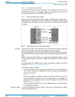
Fig. 5-5:
Block diagram: Function of the Ethernet interface
ICR845-2
PC
Aux
Host
CAN
Ethernet
CLV-Setup
FTP Server
Port 21: FTP
Port 2112: Host
Port 2111: AUX
RS 232
RS 232/422


