


Chapter 5
Operating Instructions
ICR845-2 Image Code Reader
44
©
SICK AG · Division Auto Ident · Germany · All rights reserved
8012377/ 0000/ 2008-01-30
Electrical installation
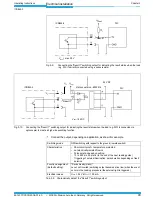
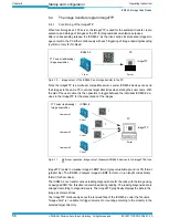
Connecting the "Result 2" switching output:
Connect the output as shown for example.
Important
If the "Device Ready" function is chosen, the ICR845-2 outputs a static pulse in Reading
mode.
Recommendation
To check the switching functions using a high-impedance digital voltmeter, wire the out-
puts with a load resistor to prevent incorrect voltage values/voltage statuses from being
displayed.
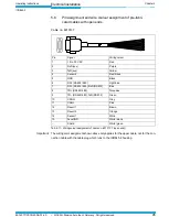
Fig. 5-11:
Connecting the "Result 2" switching output
ICR845-2
V
S
= 15 to 30 V DC
V
out
"Result 2"
V
S
R
L
= Resistance of the
connected circuit
R
L
Switching mode
PNP-switching with respect to the power supply V
S
(high-side switch)
Characteristics
– Short-circuit-proof + temperature protected
– not electrically isolated from V
S
– Pulse duration based on setting:
10 to 990 ms, 00: static (to the end of the next reading pulse)
Function assignment
(default setting)
"Good Read" (100 ms),
Level: not inverted (switching output becomes alive (high) when the event
occurs in the reading procedure)
Electrical values
(V
S
1.5 V
V
out
< V
S
at I
out
100 mA
Tab. 5-10: Characteristic data of the "Result 2" switching output


