


Operating Instructions
Chapter 8
ICR845-2
Troubleshooting
8012377/0000/2008-01-30
©
SICK AG · Division Auto Ident · Germany · All rights reserved
111
2. Pulse mode:
Serial Interface
The ICR845-2 cannot be pulsed:
– the "Laser On" LED does not light up
– the red illumination field (pulsed)
does not appear
Incorrect reading pulse source parame-
terized on the ICR845-2
Incorrect commands use
The ICR845-2 is not receiving any com-
mand strings to start the reading interval
on the data interface.
Check with CLV-Setup:
Select the D
EVICE
C
ONFIGURATION
tab, click
the R
EADING
T
RIGGER
P
ARAMETERS
button.
In the S
TART OF READING INTERVAL
section:
is serial interface selected?
S
ERIAL
I
NTERFACE
section:
Is trigger type correct?
Use correct commands.
Standard trigger:
Start: <START>21<STOP>
Stop: <START>22<STOP>
– or –
defined single characters (D
EVICE
C
ONFIG
-
URATION
tab, click the R
EADING
T
RIGGER
P
A
-
RAMETERS
button, S
ERIAL
I
NTERFACE
section).
Check data connection to host.
Check with CLV-Setup:
Select the H
OST
I
NTERFACE
tab.
D
ATA
F
ORMAT
section:
are the correct interface type (hardware)
and data format selected?
I
NTERFACE
P
ROTOCOL
section: are the cor-
rect start and stop characters selected?
Use CLV-Setup to check the host com-
mand strings:
Select the A
UXILIARY
I
NTERFACE
tab. Select
the M
ONITOR
H
OST
I
NTERFACE
function (see
Chapter 6.9.5 Monitor Host Interface,
Page 84
).
Download temporarily to the ICR845-2.
3. ICR845-2 does not respond to an exter-
nal signal that ends the reading pulse
(Pulse mode: sensor input(s), serial inter-
face)
Trigger mode: one external sensor
Incorrect end of reading pulse parame-
terized on the ICR845-2
Signal/no signal from the sensor at the
"Sensor 1" input
Trigger mode: two external sensors
If "Sensor 2" switching input is selected
as trigger source for end of reading inter-
val: no sensor connected or end of read-
ing interval configured incorrectly
The object does not pass the reading
pulse sensor for trigger stop with the
conveyor running
Illumination timeout exceeded.
Check with CLV-Setup:
Select the D
EVICE
C
ONFIGURATION
tab, click
the R
EADING
T
RIGGER
P
ARAMETERS
button.
E
ND OF READING INTERVAL
section: is
"Trigger Source" selected?
Check wiring of the sensor:
Measure output signal of sensor.
Connect sensor to "Sensor 2" switching
input. Check sensor wiring (see
Chapter 5.5.6 Connecting the switching
inputs, Page 41
).
Check with CLV-Setup:
Select the D
EVICE
C
ONFIGURATION
tab, S
EN
-
SOR
2 section: Assignment: is "Reading
trigger stop" selected, is "not inverted"
(active high) selected?
(Active high: current at input stops read-
ing interval, active low: reading interval
stops when power removed)
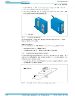
Install the sensor for stopping the read-
ing pulse in front of the sensor for start-
ing the reading pulse in conveyor
direction.
See remedy in
Tab. 8-3, Seite 109
Fault
Possible cause
Remedy
Tab. 8-4: Troubleshooting: Reading pulse errors in Reading mode (contd.)