


Operating Instructions
Chapter 5
ICR845-2
Electrical installation
8012377/0000/2008-01-30
©
SICK AG · Division Auto Ident · Germany · All rights reserved
39
Damage to the interface module!
Incorrect wiring of the serial host interface can damage electronic components in the
ICR845-2.
Observe information about wiring the host interface.
Check the wiring carefully before switching on the ICR845-2.
1.
Connect the serial host interface on the ICR845-2 to the host computer using shielded
cables (EMC requirements). Ensure that the maximum cable lengths are not exceeded
(
Table 5-7
).
2.
To prevent interference, do not lay the cable parallel with power supply and motor ca-
bles over long distances, e.g. in cable ducts.
Terminating the RS 422 interface
The interface can be terminated in the CDB620 or CDM420 Connection Module.
See "CDB620 or CDM420 Connection Module" Operating Instructions.
In the default setting, the ICR845-2 communicates with the host computer via the serial
host interface using the values shown in
Chapter 6.11 Default settings, Page 91
.
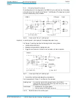
5.5.3
Connecting the serial auxiliary interface
The ICR845-2 is configured and diagnosed with the CLV-Setup configuration software. In or-
der to do so, you must connect the device to the PC via the serial auxiliary interface.
Alternatively, you can use the Aux port of the Ethernet interface.
The serial auxilary interface of the ICR845-2 can be operated as an RS 232 interface. The
cable length between the connection module and the ICR845-2 must not exceed 10 m
(32.8 ft). Unlike the serial host interface, the serial auxiliary interface has a fixed data for-
mat and a fixed data transfer rate..
1.
Switch off the PC and power supply to the connection module.
2.
Connect the PC to the internal, 9-pin "Aux" plug of the connection module.
To do so, use a 3-core RS 232 data cable (null modem cable, RxD and TxD crossed),
e.g. no. 2014054.
– or –
Without the SICK Connection Module:
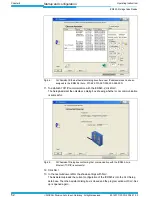
Connect the PC as shown in
Fig. 5-4
.
In the default setting, the ICR845-2 communicates via the serial auxiliary interface using
the values shown in
Chapter 6.11 Default settings, Page 91
.
Fig. 5-4:
Connecting the serial auxiliary interface
RS 232
ICR845-2
PC
( ) = 9-pin D-Sub
plug on the PC


