


Operating Instructions
Chapter 10
ICR845-2
Appendix
8012377/0000/2008-01-30
©
SICK AG · Division Auto Ident · Germany · All rights reserved
133
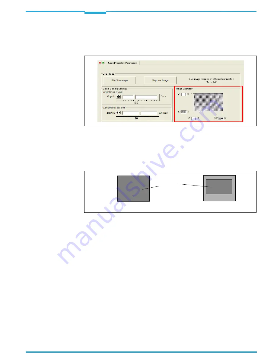
e) Image geometry
1.
Select the R
EADING
C
ONFIGURATION
tab (
Fig. 10-5, Page 129
).
2.
Click the C
ODE
P
ROPERTIES
P
ARAMETERS
button.
The C
ODE
P
ROPERTIES
P
ARAMETERS
dialog box is then displayed.
3.
When objects are conveyed in a consistent manner and the code is in the same position
on the objects, you can reduce the matrix sensor area to be evaluated by entering the
relevant percentage values in the I
MAGE GEOMETRY
section.
Sample:
Y1 = 20 %, Y2 = 70 %; X1 = 10 %, X2 = 80 %
Important
The limitation of the matrix sensor area for the selected values is not displayed graphically
in the dialog box.
f) Resolution
1.
Select the R
EADING
C
ONFIGURATION
tab (
Fig. 10-5, Page 129
).
2.
Click the C
ODE
P
ROPERTIES
P
ARAMETERS
button.
The C
ODE
P
ROPERTIES
P
ARAMETERS
dialog box is then displayed.
3.
In the R
ESOLUTION
section, switch from
HIGH
to
LOW
(if necessary) (
Fig. 10-13, Page 134
).
Fig. 10-11: CLV-Setup: "Code Properties Parameters" tab
Fig. 10-12: Limiting the active image recording area of the matrix sensor
Y1 = 0 %
Y2 = 100 %
X1 = 0 %
X2 = 100 %
Y1 = 20 %
Y2 = 70 %
X1 = 10 %
X2 = 80 %
active
field of
view


