


Chapter 6
Operating Instructions
ICR845-2 Image Code Reader
74
©
SICK AG · Division Auto Ident · Germany · All rights reserved
8012377/ 0000/ 2008-01-30
Startup and configuration
6.9
Operating modes and outputting the reading result
The following ICR845-2 operating modes/functions can be selected in CLV-Setup:
Standard operating mode
Reading mode
For startup
Percentage Evaluation
For adapting device to application
Configuration (parameterizing)
(see
Chapter 6.8 Configuring the ICR845-2, Page 71
)
Teach-in match code 1/activating match code comparison with "Sensor 2" switching in-
put (see
Chapter 10.7.1 Triggering the Teach-in match code 1 and activating the code
comparison via the "Sensor 2" switching input, Page 149
)
For monitoring purposes/correcting faults
Image acquisition (Ethernet interface)
Reading diagnosis
Monitor host interface
Displaying and editing operating data
Auxiliary input
Code statistics for RDT400
Self-test
Monitor (communication between CLV-Setup and ICR845-2)
6.9.1
Reading mode (standard operating mode)
The ICR845-2 performs a self-test after it has been switched on. The start of Reading mode
is confirmed with two consecutive tones from the beeper.
Default setting
In the default setting, the "Sensor 1" switching input is the (external) trigger source of the
reading pulse. The ICR845-2 only reads 2D codes. The ICR845-2 outputs the reading result
at the end of the reading pulse, in the default setting, via the host and auxiliary interfaces.
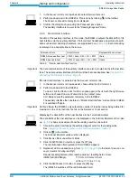
After a Good Read the "Result" LED lights up for a duration of 100 ms.
Depending of the configuration, the "Result 1" and "Result 2" switching outputs become live
for the predefined pulse length when defined events occur during the reading process (e. g.
Good Read).
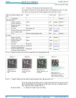
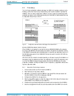
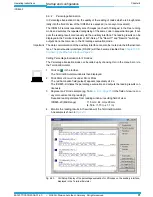
Reading result of the auxiliary interface
The reading result of the auxiliary interface can be displayed in the CLV-Setup Terminal Em-
ulator. For this, the auxiliary interface of the ICR845-2 must be in "Reading Diagnosis"
mode. This mode is selected for the default setting. The reading result of the auxiliary inter-
face has a fixed, invariable format.
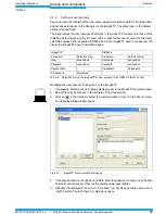
The data communication of the auxiliary interface can also be routed via the Ethernet inter-
face. The physical auxiliary interface (RS 232) will then become disabled. See
Chapter 5.5.5
Connecting the Ethernet interface, Page 40
.
Important
For 1D code (bar code) reading, the corresponding bar code type must be activated for eval-
uation beforehand (all bar code types are deactivated in the default setting).
The length of the readable code is reduced with respect to the decodable length as a result