


Chapter 6
Operating Instructions
ICR845-2 Image Code Reader
84
©
SICK AG · Division Auto Ident · Germany · All rights reserved
8012377/ 0000/ 2008-01-30
Startup and configuration
1.
In the A
UXILIARY
I
NTERFACE
drop-down list, select R
EADING
D
IAGNOSIS
.
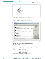
2.
Perform a download to the ICR845-2. This is done by clicking
in the toolbar.
The D
OWNLOAD
P
ARAMETER
dialog box is displayed.
3.
Confirm the dialog box by selecting the P
ERMANENT
save option.
The auxiliary interface is now set to the "Reading Diagnosis" mode.
6.9.5
Monitor Host Interface
Function of the auxiliary interface. In this mode, the ICR845-2 outputs the data traffic of its
host interface via the auxiliary interface. Protocol driver handshakes and protocol-specific
data, such as start and stop characters, are suppressed here (
Table 6-9
). Each data string
is displayed on a separate line on the screen.
Important
The data communication of the auxiliary interface can also be routed via the Ethernet inter-
face. The serial auxiliary interface (RS 232) will then become disabled. See
Chapter 5.5.5
Connecting the Ethernet interface, Page 40
.
"Monitor Host Interface" is activated via the A
UXILIARY
I
NTERFACE
tab.
1.
In the A
UXILIARY
I
NTERFACE
drop-down list, choose M
ONITOR
H
OST
I
NTERFACE
.
2.
Perform a download to the ICR845-2.
To do so, click the M
ONITOR
H
OST
I
NTERFACE
option again in the list with the right mouse
button and choose D
OWNLOAD
P
ARAMETER
in the context menu.
CLV-Setup copies the parameter temporary to the ICR845-2.
The auxiliary interface then operates in "Monitor Host Interface" mode until the ICR845-
2 is switched off again.
Important
On Good Read, the ICR845-2 only outputs the number of read bar codes being defined for
maximum on the C
ODE CONFIGURATION
tab, in the N
UMBER OF
C
ODES
section.
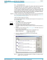
Displaying the data traffic of the host interface in the Terminal Emulator
The data traffic of the host interface can be displayed in the Terminal Emulator of CLV-Set-
up.
Fig. 6-25
shows an example of how the reading result can be output.
1.
Choose the serial interface as the external trigger source for the reading pulse.
See
„Triggering the reading pulse via the Terminal Emulator“, Seite 79
.
2.
Click on
in the toolbar.
The Terminal Emulator window is then displayed.
3.
Click R
EADING
M
ODE
under D
EVICE
M
ODE
.
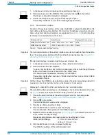
4.
Click the SW-T
RIGGER
O
N
button or press the [F7] key.
The red illumination field (pulsed) of the ICR845-2 appears
5.
Represent a 2D code sample (e.g. from
Fig. 6-18, Page 75
)
in the field of view (no con-
veyor movement during reading!)
Required reading distance from reading window / resulting field of view:
ICR845-2C (Mid Range):
115 mm / 44 mm x 28 mm
(4.53 in / 1.73 in x 1.1 in)
6.
Click the SW-T
RIGGER
O
FF
button or press the [F8] key.
The ICR845-2 switches off the red illumination field.
Direction of data
Output format
Representation on screen
ICR845-2 receives from host
<STX> I data <CR> <LF> <ETX>
I data
ICR845-2 sends to host
<STX> O data <CR> <LF> <ETX>
O data
Tab. 6-9: "Monitor Host Interface" function


