96
4. Parameter description
Parameter
K0
K1
STF(P.8X=0)
STR(P.8X=1)
SD
K0
K1
Operating
Instructions
0
1
0
1
1
1
0
0
Stop
Run Forward
Run Reverse
Stop
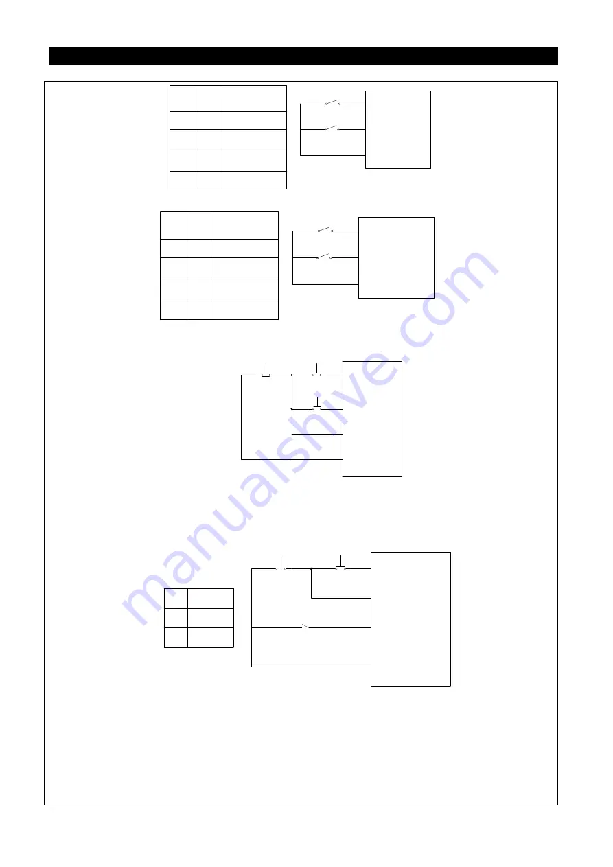
(2). two-wire control mode2:
K0
K1
RUN(P.8X=28)
STF/STR(P.8X=29)
SD
K0
K1
Operating
Instrnctions
0
1
0
1
1
1
0
0
Stop
Run Forward
Run Reverse
Sop
(3). three-wire control mode2 (with self maintaining function):K1: STOP signal, normally close. If it is
open, the inverter will stop. K2: RNU signal, normally open, and the pulse signal is active.
STOP(P.8X=31)
K0
K2
K1
STR(P.8X=1)
STF(P.8X=0)
SD
(4). three-wire control mode2 (with self maintaining function):K1: STOP signal, normally close. If K1
opened, the inverter will stop. K2: RNU signal, normally open, and the pulse signal is active. If the
external terminal corresponding related parameters settings for 39, when reversing, the motor will stop
until you start again.
STOP(P.8X=31)
K0
K2
K1
STF/ STR(P.8X=29)
RUN(P.8X=28)
Operating
Instruction
SD
K0
1
0
Run Forward
Run Reverse
5. In external mode, when PO is ‘on’, the programmed operation mode is chosen. Terminal STF becomes the
start signal. When STF is ‘on’, the inverter begins to run in programmed operation mode at the first
section. When STF is ‘off’, the inverter stops running, and STR becomes the pause signal. When STR is
‘on’, the inverter pauses and continues to run at the section where the inverter paused when STR is ‘off’.
For details, please refer to P.100, P.101~P.108, P.111~P.118, P.121~P.123 and P.131~P.138.
6. In external mode, when MPO is ‘on’, the manually operation circle mode is chosen. For details, please
refer to P.100, P.101~P.108, P.111~P.118, P.121~P.123 and P.131~P.138.


