


Intelli-FLEX II processor settings
Intelli-FLEX II product guide • • • 5 - 39
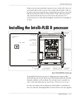
Intelli-FLEX II processor settings
Once all of the components have been installed, the processor jumpers can be set
and the wires can be connected.
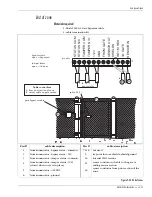
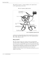
Jumper settings
The factory setting has shunts installed at JP1 through JP6.
JP-1 and JP-2 Local supervision
•
Remove the shunt at JP-1 if a properly terminated sensor cable is to be
connected to Zone 1.
•
Remove the shunt at JP-2 if a properly terminated sensor cable is to be
connected to Zone 2.
If the sensor cable is disconnected, replace the
appropriate jumper (i.e., JP-1 for zone 1). This can be
helpful in locating cable faults.
JP-3 Unused processor A/D inputs
•
Three jumpers hold the inputs to three A/D inputs on the microprocessor at
0 VDC.
DO NOT remove this shunt unless specifically
instructed.
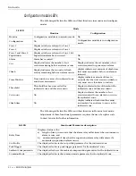
Figure 5-37 Processor jumpers


