


Perimeter layout guidelines
4 - 12 • • • Intelli-FLEX II product guide
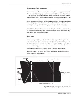
Drip loops
Drip loops must be placed at every cable connector. The drip loop raises the
terminator or splice above the cable. This prevents water from pooling in the
terminator gel shell. The drip loop also relieves strain on the splice connection
that may result from temperature change that causes the cable to expand and
contract.
A drip loop is formed by raising the cable connector a 15 cm (6 in.) above the
level of the cable run, to a local high point.
Figure 4-9 Drip loop
Approximately 15 cm (6 in.) of cable should be allotted for each drip loop.
Non-sensitive feed cable
The maximum length of non-sensitive feed cable for 305 m (1,000 ft.) of sensor
cable must be in accordance with the non-sensitive feed cable lengths table.
Table 4-1 Non-sensitive feed cable lengths
The non-sensitive feed cable should have a solid center conductor 0.6 mm (0.023
to 0.025 in.) in diameter to fit the coaxial F-connector on the processor.
The maximum length of non-sensitive feed and bypass cables may be extended,
provided the length of the Intelli-FLEX sensor cable is reduced accordingly.
Non-sensitive cable type
Maximum length
RG-59/U, 69 pf/m (21 pf/ft.)
116 m (380 ft.)
RG-62/U, 43 pf/m (13 pf/ft.)
186 m (610 ft.)
15 cm
(6 in.)
sensor cable
splice kit enclosure
drip loop


