


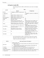


Intelli-FLEX II processor settings
5 - 46 • • • Intelli-FLEX II product guide
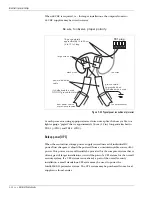
When 48 VDC is required, i.e., for larger installations, the outputs from two
24 VDC supplies may be wired in series.
Be sure to observe proper polarity.
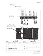
At each processor, using appropriate sized wire nuts, splice the heavy cable to a
lighter gauge “pigtail” that is approximately 30 cm (12 in.) long and attached to
TB1-1 (+VDC) and TB1-2 (-VDC).
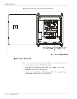
Backup power (UPS)
When the central low voltage power supply is used instead of individual DC
power/float chargers, it should be powered from a non-interruptible source of AC
power. This power source will usually be provided for the computer system that is
often a part of larger installations, or it will be part of a UPS system for the overall
security system. If a UPS system is not already a part of the overall security
installation, a small standalone UPS system may be used to power the
Intelli-FLEX II perimeter system. The UPS system may be purchased from a local
supplier or from Senstar.
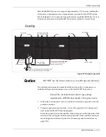
Figure 5-44 Typical power connection at processor
to next processor
from power source
or previous processor
black wires
red wires
TB1 plug
18 gauge pigtails
approximately 15 to 30 cm
(6 to 12 in.) long
large wire nuts
power distribution
cable
ground shield
to grounded box
if shielded wire is used
if shielded cable is used
DO NOT ground this shield


