


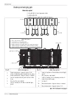
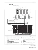


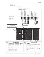


Gate bypass module
Intelli-FLEX II product guide • • • 5 - 29
Model 2490-2 - Remote gate bypass module
Operation
Remote operation from the monitor and control system requires a 12 VDC input
to energize the bypass relay, provided by the control system. When the relay is
energized the sensor cable is shunted around the gate or terminated at the gate,
depending on the particular configuration; and the status contacts close giving a
signal to an annunciation device.
If the cover is removed from the bypass housing, a tamper switch will open,
supporting an indication, when wired appropriately, to an annunciation device.
Interface
The terminal block is a 12-position, stripped bare-wire, screw-clamp style device
which does not require crimp lugs or special hardware connections. The
connections to the annunciation device are consistent regardless of bypass
configuration on the gate or fence. These connections are typically fed through
conduit, off the fence, underground, to the transponder housing for interface to
the annunciator, or to the local key box mounted for convenient access from
vehicles, or the walkway.
Connection details are given for each situation in the following sections.
Figure 5-29 Remote gate bypass module terminal block
CR1
ST
ATUS
N/C
ST
ATUS
COM
VR1
INT
1M
RES
+12V
TAMPER
COM
TAMPER
N/O
GND
SENSOR
OUT
FROM
GA
TE
K1
TO
GA
TE
SENSOR
IN
TB1
SHIELDS


