


Gate bypass module
5 - 32 • • • Intelli-FLEX II product guide
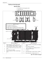
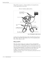
Sliding Gate
Materials required
1 - Model 2490-2 Gate bypass module
3 - cable splice kits
2 - gate disconnects
1 length of non-sensitive feed cable for bypass
Figure 5-32 Sliding gate
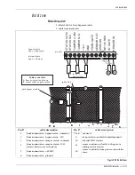
Pin #
cable description
Pin #
cable description
1
from annunciator - bypass status - common
7
center conductor of return from gate or
bypassed section
2
from annunciator - bypass status - N/C
8
center conductor to continuing section of
sensor
3
from annunciator - tamper status - common
9
tie point for coax shields
4
from annunciator - tamper status - N/O
(closed when cover is in place)
10
not used
5
from annunciator -+12 VDC
11
center conductor of cable to the gate or
bypassed section
6
from annunciator - ground
12
center conductor from prior section of the
zone
C
A
B
D
E
ST
ATUS
COM
TAMPER
N/O
TAMPER
COM
ST
ATUS
N/C
FROM
GA
TE
+12V
GND
SENSOR
OUT
INT
1M
RES
SHIELDS
SENSOR
IN
TO
GA
TE
B
A
E
D
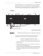
Cable connections
A from prior section of zone
B non-sensitive cable from bypass module
to gate section via disconnect assembly
C sensor cable on gate section
D
from gate section to
bypass module via
E bypass cable from bypass module to
sensor cable beyond gate
non-sensitive cable
disconnect assembly
gate bypass module
splice kit (3)
pin outs
to
annunciator
to
from
1
12
disconnect
assembly (2)


