


Installation of cable at gates
Intelli-FLEX II product guide • • • 5 - 17
To determine the amount of RG-59 required for the sliding gate installation refer
to
Figure 5-18, Determining RG-59 length requirements,
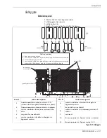
In some instances, it may be necessary to install an
L-bracket, as a cable guide bar, to prevent the coaxial
cable from being jammed between the gate and the
fence panel.
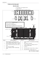
Single panel sliding gate on inside of perimeter
Figure 5-19 Single sliding gate on inside of perimeter
Cable connections
A sensor cable from prior section of
zone
B
from previous
fence section to gate section between
splice kits
C sensor cable on gate section
D non-sensitive bypass cable from prior
section to sensor cable beyond gate
non-sensitive cable
C
B
splice kit
cable secured to gate
section at this point
RG-59 cables
max. width = 4 X fence height
fence
height
splice kit (2)
splice kit (2 located
in center of gate width)
gate open
gate closed
2 non-sensitive
RG-59 cables
bundled together
A
D
direction to slide open


