


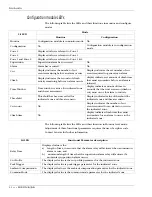


Intelli-FLEX II processor settings
5 - 42 • • • Intelli-FLEX II product guide
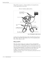
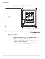
Wiring connections
Once the jumpers have been set, proceed to make the wiring connections at the
processor as follows:
1. Feed the non-sensitive feed cable from inside the enclosure, through the
gland fittings to the sensor cable.
The F-connector will not fit through the gland fitting.
2. Splice together the non-sensitive feed cable and the sensor cable. (See cable
splice directions)
3. Connect the non-sensitive feed cable for Zone 1 to J1.
4. Connect the non-sensitive feed cable for Zone 2 to J2.
On large installations with many zones, connect the
lower number zone to zone 1 and the higher number to
zone 2 of the processor.
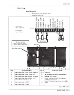
Power connections
DC power/float charger
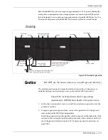
Figure 5-40 Powering a single Intelli-FLEX II processor
The battery may be supplied with different colored leads
(e.g., black-negative, black with white stripe-positive). If the
wire color is different than what is specified in this figure, use
a meter to confirm the polarity.


